
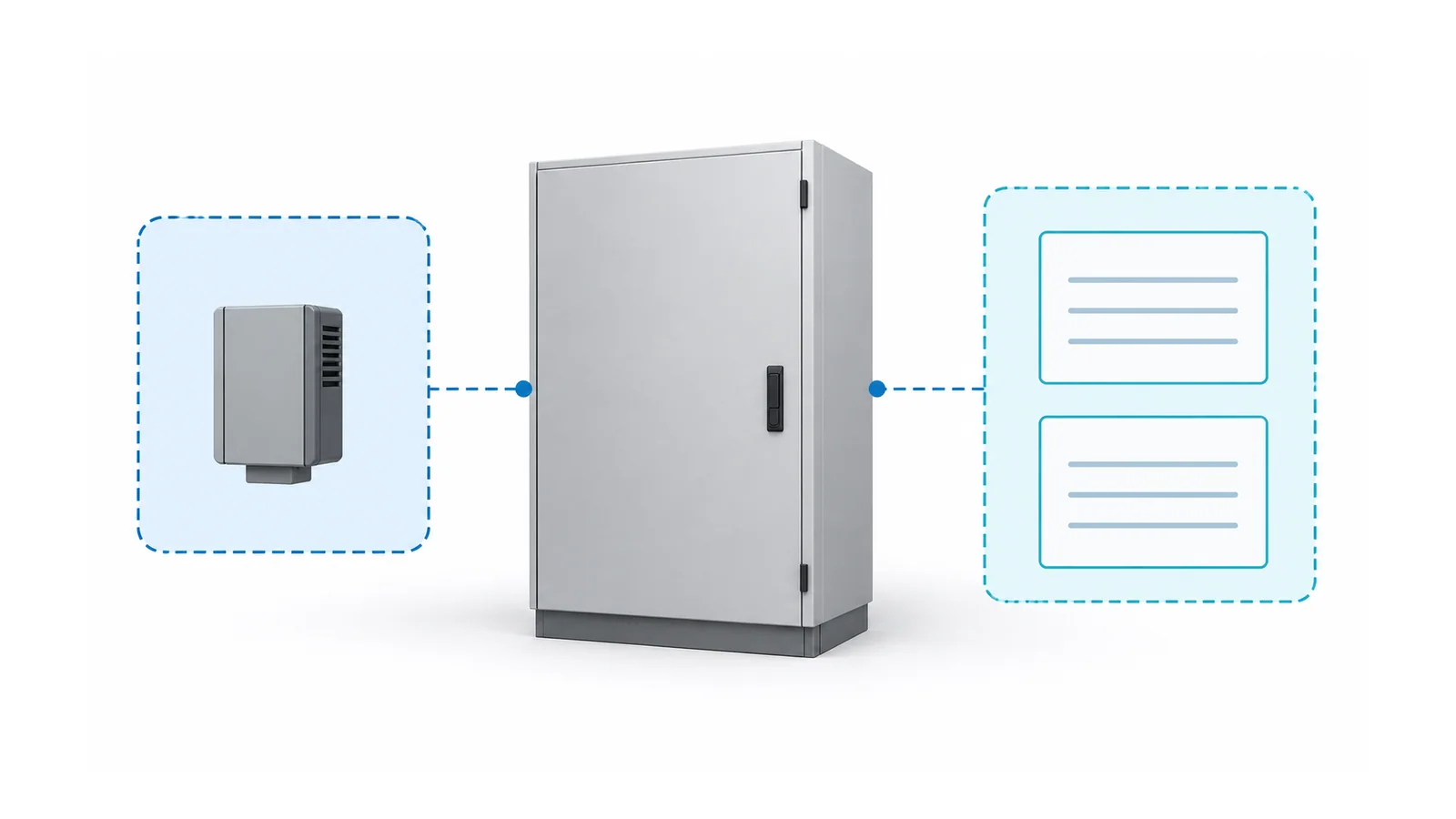
Specify intelligent breakers and switchgear by electrical duty first, then by demonstrable digital functions. For each measurement, alarm or command, define the operating purpose, required data, failure behavior and acceptance test. “Smart,” “connected” and a protocol name are not complete requirements.
This checklist covers industrial low-voltage (LV) assemblies using an International Electrotechnical Commission (IEC) standards framework. It is not a residential smart-switch guide or a medium-voltage protection-network design. The deliverable is a function-to-test schedule that the plant’s electrical, automation and operational-technology teams can jointly accept.
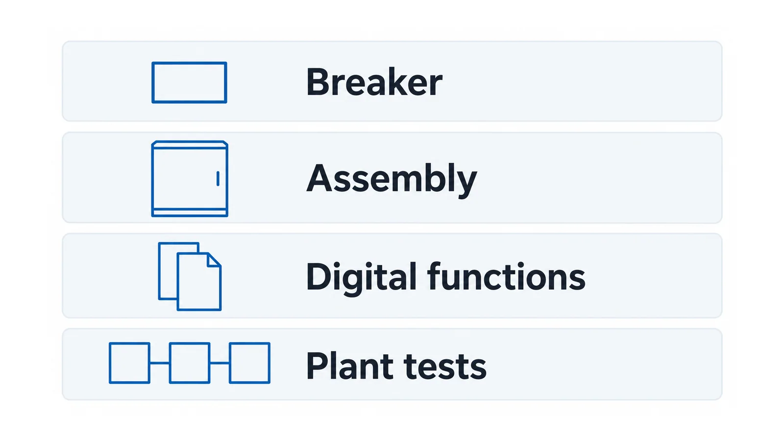
Separate four acceptance layers
| Layer | What is being accepted | Evidence that belongs here |
|---|---|---|
| Breaker | Electrical interruption, protection and declared accessories | Correct duty, applicable device evidence, settings responsibility and accessory behavior |
| Assembly | The complete switchgear configuration | Applicable assembly verification, interfaces and installation conditions |
| Digital functions | Measurements, events, health indications and commands | Defined data semantics, accuracy basis, failure response and functional tests |
| Plant integration | Use of those functions in the actual system | Network, permissions, time quality, control ownership and end-to-end acceptance |
IEC 60947-2:2024 covers the relevant industrial LV circuit-breaker device scope. IEC 61439-1:2020 supplies general assembly rules used with the applicable product part; IEC 61439-2:2020 addresses power switchgear and controlgear assemblies. A compliant component does not by itself establish complete-assembly conformity. IEC breaker scope, IEC assembly general rules, IEC power-assembly scope
For the added digital layer, IEC TS 63290:2024 specifically provides supplementary requirements for intelligent assemblies within its IEC 61439 scope. It is not a substitute for their electromechanical requirements. Record the editions and applicability adopted by the project; the public catalogue descriptions are scope references, not proof that a proposed product passed the necessary verification. IEC TS 63290:2024
Establish the electrical baseline before adding features
Record system voltage and frequency, load duty, prospective fault conditions, protection coordination, environmental conditions and assembly interfaces. Use molded-case circuit-breaker basics for the device terminology, and the LV circuit-breaker selectivity guide for the separate coordination task.
Digital convenience must not obscure the approved protection basis. Identify which functions reside in the trip unit, which depend on auxiliary power, and which depend on gateways or external software. Do not assume every intelligent breaker has the same architecture—or that a network failure necessarily disables or leaves unchanged every function.
For an existing installation, establish whether the intended work is repair, retrofit or replacement before specifying the new digital scope. That lifecycle decision is covered in aging switchgear: repair, retrofit or replace.
Write a function-to-data-to-test matrix
The following is an editorial specification framework, not a reproduced standards checklist. Replace each example with the plant’s required values, operating states and acceptance limits.
| Required function | What the specification must resolve | Acceptance evidence |
|---|---|---|
| Current, voltage or energy measurement | Quantity, units, scaling, accuracy conditions, update rate and unavailable-data indication | Compare against an agreed reference and check the complete exported data path |
| Breaker status and trip events | Meaning of each state, distinction between open and tripped, timestamp source and event retention | Safely simulate agreed states; confirm local and supervisory indications agree |
| Temperature or condition indication | Sensor location, measured versus inferred value, algorithm inputs and alarm logic | Demonstrate sensor/data failures and the declared alarm response; document model limitations |
| Remote commands, if required | Authority, local/remote modes, interlocks, feedback and loss-of-communication response | Execute an approved test plan in a controlled safe configuration; verify rejected and permitted requests |
| Historical data export | Retention, export format, clock behavior, replacement-device continuity and ownership | Export a representative record and recover it without the original dashboard |
| Maintenance or firmware support | Supported versions, access method, change approval, recovery and end-of-support responsibilities | Review support records; demonstrate backup/recovery and an agreed controlled update process |
For every row, name the evidence owner. An unspecified “integration by others” leaves the most important boundary unresolved: who proves that the delivered function works at the plant interface?
Specify data meaning, not just transport
A supported protocol does not guarantee that two systems interpret the same information. Document the actual point list and version: addresses or identifiers, units, scaling, valid range, quality flag, timestamp meaning and control permissions.
Distinguish a current measurement from a stored peak, an event timestamp from the time a server received it, and an estimated contact condition from a direct temperature measurement. If a dashboard presents derived health information, retain its input assumptions and limitations in the acceptance file.
Make stale, missing and invalid data visibly different from a genuine zero or normal status. Require a test of that distinction across the full interface, rather than a screenshot from one device display.
Define failures before approving remote capability
Review loss of network, loss of auxiliary supply, gateway restart, clock loss and replacement of a digital module. For each, specify the intended outcome separately for protection, indication, logging and commands. Use declared product architecture and verified tests; do not extrapolate the behavior of one function to all others.
Remote access is a plant operational-technology (OT) decision. The National Institute of Standards and Technology (NIST) publication SP 800-82 Rev.3 provides OT security guidance that considers reliability and safety alongside access control. Its final publication is the reference here; the later Rev.4 initial draft is not treated as a final replacement. NIST OT security guide
Translate that guidance into explicit project questions: who can connect, who can command, how access is approved and revoked, what is logged, and how the plant restores operation after a failed change. Define controlled update testing and recovery ownership. These are acceptance requirements to resolve, not a claim that a generic cybersecurity certificate covers the installed system.
Remote visibility also does not grant permission for exposed electrical work. A displayed “open” state is not verified isolation. In US general industry, Occupational Safety and Health Administration (OSHA) regulation 1910.333 addresses de-energization, lockout/tagout and qualified-person verification; other locations require their applicable procedures. OSHA electrical work practices
Divide FAT and SAT responsibilities
The factory acceptance test (FAT) can confirm the agreed configuration, simulated inputs, local behavior and defined communications interfaces. The site acceptance test (SAT) should then prove the functions that depend on the actual plant network, supervisory system, authority model and operating procedures.
Agree this division before delivery. For example, the factory may demonstrate a time-quality flag, while the site must prove that the plant system receives and displays it correctly. A factory pass cannot resolve an untested site dependency.
The controlled test plan should include expected failures and prohibited actions as well as successful operations. Electrical and remote-command tests require competent personnel, an approved safe test configuration and the site’s isolation/interlock arrangements; this article is not an operating sequence.
What belongs in the accepted handover file?
Keep the electrical duty and adopted standards, assembly/configuration identification, function matrix, point list, firmware and interface versions, failure-state results, FAT/SAT records, access ownership and recovery procedure together. Record remaining exceptions and who accepts them.
The procurement decision is complete when the plant can answer three questions: what does each intelligent function do, what happens when its dependencies fail, and who has demonstrated the behavior? A long feature list without those answers is still an unfinished specification.
Sources
- IEC 60947-2:2024, IEC 61439-1:2020, and IEC 61439-2:2020: public device and assembly scopes.
- IEC TS 63290:2024 — Supplementary requirements for intelligent assemblies: public scope.
- NIST SP 800-82 Rev.3 — Guide to Operational Technology Security: final publication, 2023.
- OSHA 1910.333 — Electrical work practices: US general-industry boundary.