
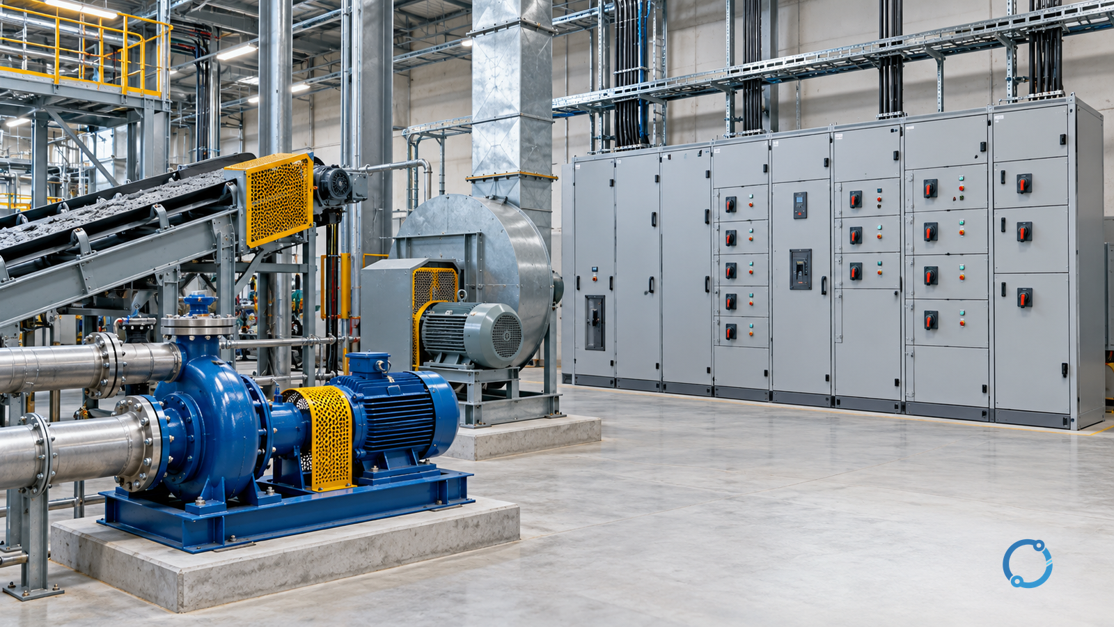
Select a motor control center (MCC) by tracing the driven machine and its operating duty through the complete electrical arrangement. Establish how each conveyor, pump, fan, compressor, mixer or crusher starts, stops, reverses and runs. Use that evidence to define functional units and starting methods. Then arrange those units into physical sections and electrically continuous bus sections that can be rated, protected, cooled, maintained and extended under actual site conditions.
A schedule containing motor kW and starter labels is only an input. This guide covers low-voltage AC MCCs for industrial mechanical loads. A complete selection connects mechanical demand to the unit schedule, the horizontal and vertical bus paths, prospective fault current, protection, environment, access and future growth. It also separates component scope from complete-assembly verification.
Start with the machine
The motor nameplate does not fully describe the mechanical task. Record torque-speed demand, breakaway torque, inertia, acceleration, normal running point and process conditions that can change the load. A conveyor may restart fully loaded; a fan may have high inertia; a crusher or mixer may jam. These are application questions, not universal rules.
Record starts and stops, acceleration time, immediate and delayed restarts, reversing or jogging, controlled stopping, required speed control, ambient conditions and the production consequence of a trip. A method that limits starting current may also reduce accelerating torque, so compare the motor and machine curves through the whole start. The motor starting methods comparison owns that screen.
Convert the duty into one schedule row for every incoming, feeder and controller unit:
| Mechanical duty | MCC input | Selection consequence |
|---|---|---|
| Accelerating torque at every speed | Motor and machine torque-speed curves | Determines which starting principles can be considered |
| Starts, reversals and stopping | Sequence, acceleration time and rest interval | Changes contactor, overload and enclosure thermal duty |
| Loaded or jammed restart | Breakaway torque, process state and restart delay | May exclude a method that cannot overcome the load |
| Run-speed requirement | Operating points, minimum speed and turndown | Separates a starter from a variable-speed drive |
| Failure consequence | Redundancy, bypass and continuity needs | Influences unit grouping, spares and isolation access |
| Control interface | Local/remote control, interlocks and control voltage | Adds devices, wiring, terminals and control-supply load |
Use actual motor and starter data for current and thermal checks. The machine-load VFD sizing guide covers torque and inertia when variable speed enters scope; the VFD selection guide covers the broader drive decision.
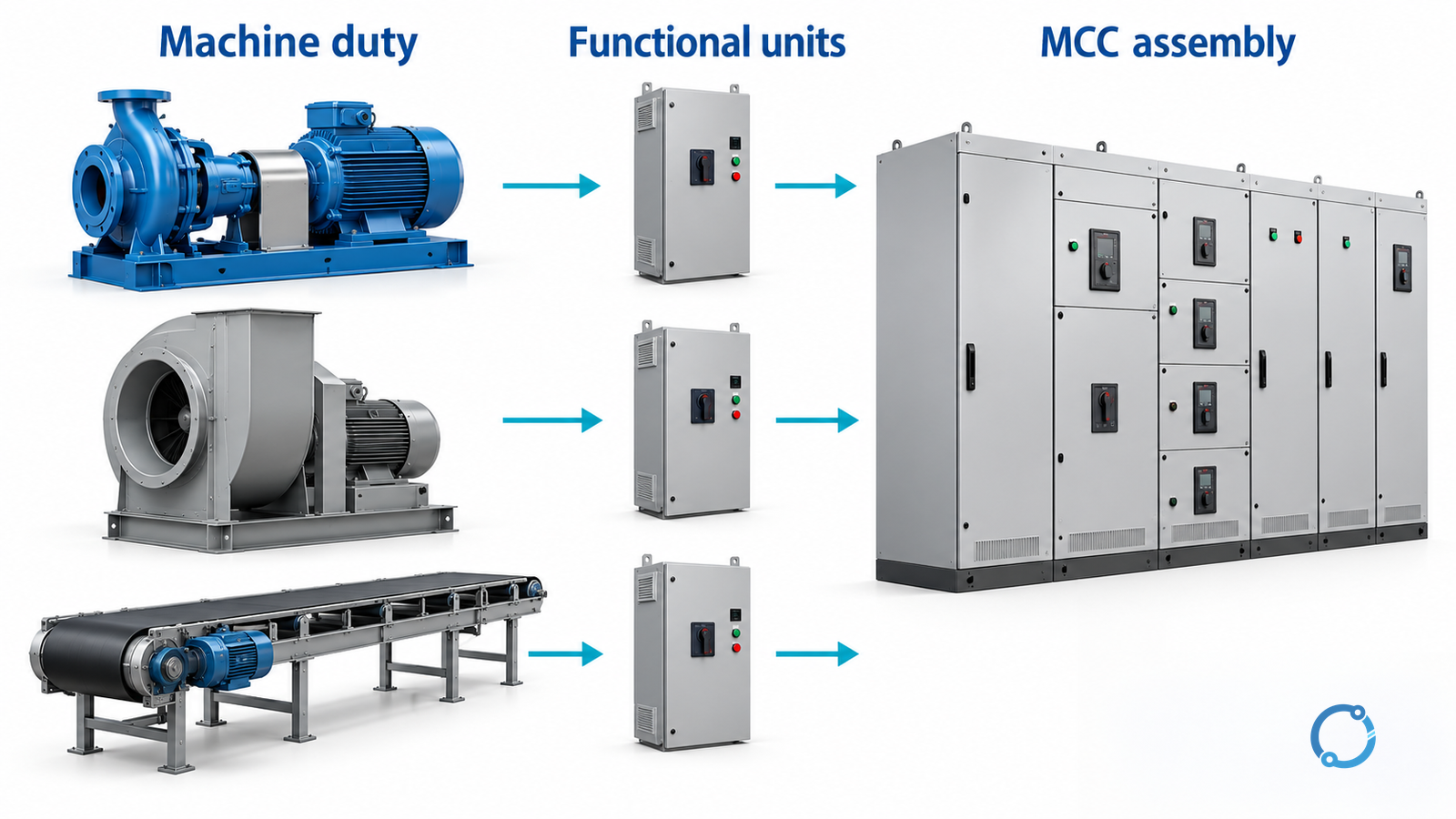
Separate three MCC layers
These terms are often interchanged, which makes a drawing difficult to review.
| MCC object | What it represents | What to confirm |
|---|---|---|
| Physical section | A structural enclosure, shipping or access division | Barriers, ventilation, cable space, unit layout and handling |
| Bus section | An electrically continuous main-bus zone | Normal and alternate feeds, current flow, fault exposure and ties |
| Functional unit | An incoming, feeder or controller assembly for one circuit | Isolation, starter, protection, terminals, control and mounting |
A section can contain several units. Adjacent physical sections may share one bus section or be electrically separated. A bus tie changes topology and fault contribution. The approved single line and general arrangement must show both physical and electrical boundaries.
Trace the power path and bus duty
Follow the source through the incoming unit, horizontal main bus, bus-section boundaries, vertical bus, functional units, outgoing terminals and cables. Record every alternate or parallel source state.
The horizontal-bus current is not necessarily the sum of all motor nameplates. It depends on connected units, operating states, diversity, spares and load flow under alternate feeds. State and approve every diversity assumption. Use starting current for voltage-drop, acceleration and switching checks, not as prospective fault current.
There is no useful universal busbar ampacity for MCC selection. Current capability depends on bar geometry and spacing, ambient, permitted temperature rise, enclosure, ventilation, mounting and the assembly’s verification method. Use the compact switchgear busbar workflow for the coupled loss and heat calculation. Include drives, soft starters, control transformers, surge devices, cable terminations and all connected buses. A larger horizontal bus does not prove the vertical bus, joints, terminals or enclosure can carry the same current. The cable feeder workflow covers the outgoing conductor calculation.
Choose the starter by behavior
The starter is part of a functional unit, not an interchangeable label.
| Arrangement | Conditional fit | Principal boundary |
|---|---|---|
| Full-voltage, non-reversing or reversing | The machine, motor, supply and switching devices accept the full-voltage event | Voltage dip, torque shock, contactor duty and protection |
| Electromechanical reduced voltage | Reduced torque and transition are acceptable at fixed speed | Starting duration and transition behavior |
| Solid-state soft starter | Managed voltage or torque during start or stop is useful at fixed speed | Reduced voltage reduces torque; bypass and semiconductor heat |
| Variable-frequency drive | Speed, torque, acceleration or stopping must be controlled | Motor compatibility, harmonics, cooling, EMC and cables |
| Feeder-only unit | The controller is elsewhere or the unit supplies another load | Isolation, protection and fault coordination at the boundary |
IEC 60947-4-1:2023 covers electromechanical contactors and starters, while IEC 60947-4-2:2020+AMD1:2024 CSV covers semiconductor motor controllers, starters and soft starters, within their stated voltage scopes. These are component standards; they do not establish the complete MCC rating or prove a particular motor-machine combination.
A soft starter does not make a fixed-speed machine variable-speed. A VFD is not only a current-limiting starter; its input current, output waveform, losses and fault behavior affect the MCC. The breaker versus contactor duty guide separates normal switching from fault interruption. The motor protection guide covers overload and short-circuit protection.
Verify withstand, then coordination
Obtain prospective fault current at the MCC and at relevant internal points for every credible source configuration, including parallel sources, bus ties, motor contribution and future modes. Do not use starting current as fault current.
Withstand asks whether the main bus, vertical buses, supports, unit connections, devices and enclosure survive the fault until clearing. This belongs to the exact complete assembly. In North America, short-circuit current rating (SCCR) is a common term. Under an IEC route, the verified assembly characteristics and applicable product-part requirements must be established. UL 845 Edition 6 is the dedicated North American MCC standard within its scope; IEC 61439-1 and IEC 61439-2 provide the general and power-assembly framework for assemblies within theirs.
Coordination asks which device clears each fault zone, whether the starter receives the protection assumed by its declared combination, and whether an upstream device remains closed where selectivity is required. See the LV breaker selectivity guide. One device’s interrupting rating does not prove MCC withstand; withstand does not prove selective operation.
Use the busbar short-circuit stress guide for support mechanics. Check that the control transformer supports simultaneous contactor pickup and holding without losing the defined safe state.
Match the room, not just the room temperature
Record ambient at the enclosure inlet, radiant heat, altitude, humidity, dust, corrosive gas, washdown, vibration, seismic requirement and hazardous-area boundaries. These conditions affect insulation, contacts, electronics, filters, gaskets and ventilation. The enclosure heat balance includes bus losses, contactors, overloads, solid-state starters, drives, control transformers, surge devices, lighting and terminations.
A VFD can add substantial heat and needs defined cooling. A fan is a design change, not a universal cure; it creates dependencies on airflow, filters and auxiliary power. Ask the MCC designer to state the temperature-rise verification method and loading pattern. Keep the actual ambient and enclosure arrangement tied to that evidence. The LV switchgear operating-temperature guide covers installed-assembly diagnosis.
Make maintenance and extension explicit
Provide front or rear access for inspection, termination, unit replacement, torque checks and testing without exposing adjacent live parts. Draw door swing, withdrawal travel, lifting route, cable bending space and the replacement-unit route. A withdrawable unit or barrier is an equipment feature, not proof of de-energization. Isolation, lockout, voltage verification, earthing where required and restoration belong to a qualified person under local procedures.
Separate every future resource: physical section, vertical-bus position, functional-unit position, horizontal-bus current, fault capability, thermal capacity, cable space and control capacity. An empty section may have no vertical bus, ventilation or fault capacity. State the future load schedule, single line and operating modes, and identify when short-circuit or temperature-rise verification must be renewed.
Apply the release matrix
The selection is complete only when each gate has evidence, an accepted assumption or a hold.
| Gate | Pass condition | Hold or reject trigger |
|---|---|---|
| Machine duty | Torque, inertia, acceleration, starts, stopping and restart cases are documented | Starter chosen from motor kW alone |
| Unit schedule | Each circuit has a unit, starter, protection, control interface and spare strategy | Similar units assumed interchangeable |
| Power path | Incoming, horizontal bus, bus sections, vertical buses and outgoing units are shown | Physical sections assumed to equal bus sections |
| Continuous duty | Unit/bus loading, voltage drop, starting duty and diversity are stated | Universal ampacity or spare percentage used |
| Fault duty | Prospective current is compared with complete-assembly evidence | One device’s rating used as MCC rating |
| Coordination | Starter protection and required selectivity are documented | Withstand and coordination treated as one check |
| Environment | Ambient, enclosure, ventilation, losses and temperature-rise basis are recorded | Component ratings assumed unchanged in the enclosure |
| Maintenance | Access, isolation, verification, withdrawal and spares are feasible | Position indicator treated as absence of voltage |
| Extension | Future loads, bus path, thermal/fault margins and re-verification triggers are stated | “Spare space” left undefined |
Complete the selection record
Retain the machine and motor schedule; duty narrative; unit schedule and starter rationale; approved single line; load-flow and diversity assumptions; fault-current study; MCC withstand evidence; coordination requirements; environmental and temperature-rise basis; maintenance and spares plan; future case; and all holds with owners and dates.
Qualified electrical engineers must apply the standards, codes and installation rules adopted for the project. This article does not authorize energized work, approve a product or replace the MCC designer’s complete-assembly verification. Its job is to make the engineering demand visible before a familiar enclosure or starter label becomes the answer.
Sources
- IEC TR 61439-0:2022 – guidance to specifying low-voltage assemblies
- IEC 61439-1:2020 – low-voltage switchgear and controlgear assemblies, general rules
- IEC 61439-2:2020 – power switchgear and controlgear assemblies
- IEC 60947-4-1:2023 – electromechanical contactors and motor-starters
- IEC 60947-4-2:2020+AMD1:2024 CSV – semiconductor motor controllers, starters and soft starters
- UL 845 Edition 6 – Motor Control Centers