
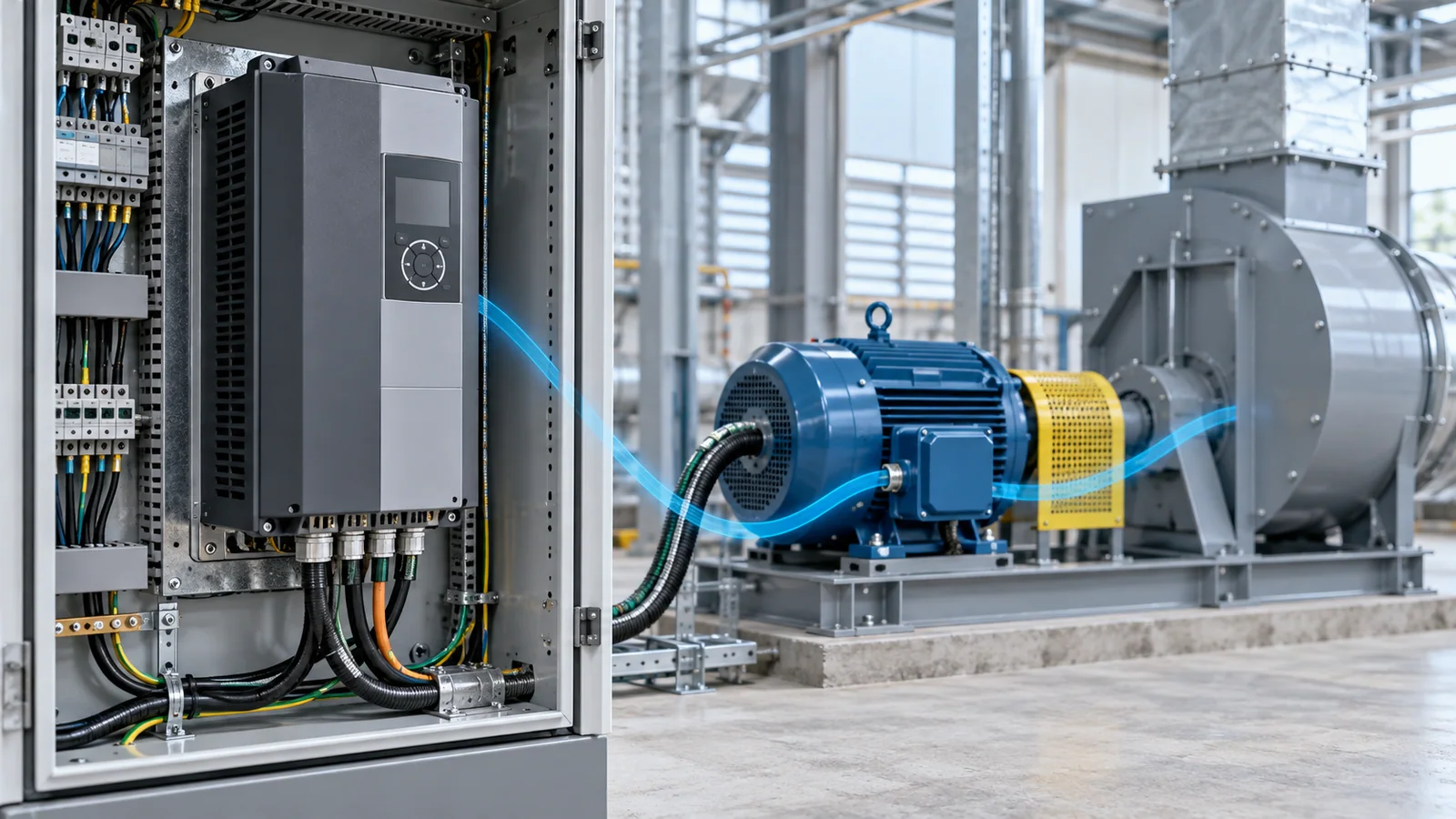
The proper variable frequency drive (VFD) is selected by matching the complete application—not simply the motor’s power rating. Start with the load’s torque–speed profile and operating cycle, then verify motor current, overload duty, speed range, braking, supply characteristics, environment, electromagnetic compatibility (EMC), harmonics, control interfaces, and required safety functions.
The final selection should be a documented power-drive-system specification that the drive, motor, driven equipment, and installation can satisfy together. IEC 61800-2:2021 follows this system view and describes selection criteria for the performance and functional attributes of adjustable-speed AC power drive systems.
Safety and scope
VFD input terminals, DC links, motor leads, braking circuits, and connected machines can retain or regenerate hazardous energy. Isolation, discharge time, absence-of-voltage verification, grounding, lockout/tagout, and commissioning must follow the applicable installation, employer procedure, local law, and equipment documentation. Parameter entry does not make an installation electrically or mechanically safe.
This guide provides a selection framework for industrial AC motor applications. It does not replace a short-circuit study, harmonic study, machinery risk assessment, hazardous-location assessment, or a manufacturer-approved application review.
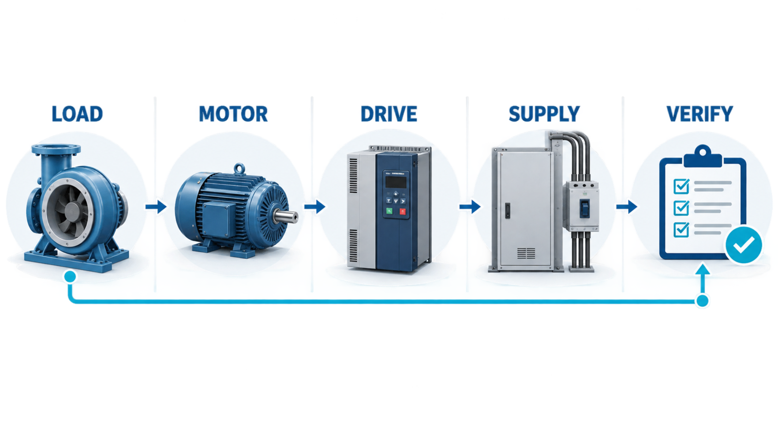
The selection sequence at a glance
Use this order:
- Define the driven load and required operating envelope.
- Confirm the motor is suitable for converter operation over that envelope.
- Select the drive by continuous output current and duty, then verify overload performance.
- Check input supply, output cable, braking, environmental, and EMC conditions.
- Specify controls, communications, protection, and safety functions.
- Validate the complete system during design and commissioning.
1. Define the load before looking at a drive catalog
Record the load’s required speed, torque, power, acceleration, deceleration, and duty cycle. A fan or centrifugal pump usually behaves differently from a conveyor, positive-displacement pump, mixer, hoist, winder, crusher, or machine-tool spindle.
The selection inputs should include:
- minimum, normal, and maximum speed;
- torque required at each important speed;
- breakaway torque and starting condition;
- acceleration and deceleration time;
- reversing, jogging, positioning, or torque-control needs;
- peak-load magnitude, frequency, and duration;
- continuous and intermittent operating periods;
- process consequences of a trip or uncontrolled coast;
- overhauling or regenerative load behavior;
- number of motors, if one drive will supply more than one.
Do not assume a VFD will save energy merely because speed control is possible. The benefit depends on the load and control method. The US Department of Energy motor-systems resources recommend assessing motor and drive system operating conditions and using variable-speed control where demand varies.
2. Match the control method to the application
The required low-speed torque, speed accuracy, dynamic response, and feedback determine the control approach.
| Application need | Control capability to evaluate |
|---|---|
| Basic variable-speed fan or pump | Scalar or other basic speed control may be sufficient when dynamic demands are modest |
| High starting torque or changing load | Sensorless vector or equivalent torque-oriented control may be appropriate if supported by the motor and drive |
| Precise speed or torque at very low speed | Closed-loop feedback and a compatible motor/encoder arrangement may be required |
| Positioning or coordinated motion | A motion-control platform may be more appropriate than a general-purpose VFD |
| Overhauling load or rapid repeated deceleration | Regenerative or dynamic-braking capability must be engineered, not assumed |
These categories are functional descriptions, not universal product labels. Confirm performance over the actual speed and torque envelope.
3. Select by current and duty—not horsepower alone
Motor power is a useful starting point, but drive output current and overload capability control many real selections. Obtain the motor nameplate data and the expected operating current across the duty cycle. Check:
- drive continuous output-current rating at the actual carrier frequency and ambient condition;
- overload current, duration, repetition, and recovery assumptions;
- motor full-load current and service duty;
- maximum operating frequency and speed limits;
- derating for altitude, temperature, enclosure, switching frequency, or installation arrangement;
- any special duty classification used by the supplier.
Avoid arbitrary oversizing. A larger drive may change protection, minimum current measurement, enclosure size, cost, and motor-control behavior. If a margin is required, tie it to a defined uncertainty or overload case.
4. Verify motor–converter compatibility
Converter operation changes the motor’s electrical and thermal environment. The IEC TS 60034-25:2022 application guide addresses AC machine performance on converter supplies and the interfaces between machine and converter, including converter-capable and converter-duty concepts, shaft-current considerations, installation guidance, and derating.
Review:
- insulation suitability for the drive waveform and installation;
- allowable speed range and mechanical maximum speed;
- cooling at reduced speed, especially for shaft-mounted fans;
- torque capability and temperature rise across the duty cycle;
- bearing-current risk and the grounding or filtering strategy;
- cable length and reflected-wave effects;
- encoder, temperature sensor, and brake compatibility;
- operation of an existing motor that was not originally specified for converter supply.
The motor, cable, and drive form one high-frequency system. A motor that operates correctly on a short lead may require a different output strategy on a long lead.
5. Check the incoming supply
Document:
- nominal voltage, frequency, and phase;
- permitted voltage variation and unbalance;
- available short-circuit current and upstream protective device;
- grounding or earthing arrangement;
- transformer size and source impedance;
- generator or weak-grid operation;
- existing capacitors, harmonic filters, or power-factor equipment;
- line disturbances and ride-through requirements.
Then verify the drive input rating, protection, disconnecting means, coordination, and any line reactor, input filter, or transformer requirements. Do not add power-factor capacitors on a VFD output unless the complete arrangement is specifically engineered and approved for that use.
6. Engineer stopping and braking
The motor and load can return energy to the DC link during deceleration or overhauling operation. Define whether the process may coast, requires controlled deceleration, or must repeatedly absorb regenerated energy.
Possible architectures include:
- coast or ramp stop within the drive’s normal capability;
- dynamic braking with a correctly rated switching unit and resistor;
- regenerative front end or common DC-bus solution;
- mechanical holding or service brakes integrated with the control sequence.
Stopping method and machinery safety are separate questions. A VFD stop command alone may not provide isolation, holding, or the required safety integrity.
7. Account for the installation environment
Specify the real installation rather than relying on a generic enclosure description:
- ambient temperature and altitude;
- humidity, condensation, dust, fibers, oil mist, salt, corrosive gas, and vibration;
- indoor, outdoor, washdown, or hazardous-location conditions;
- enclosure ingress protection and cooling method;
- available cabinet ventilation and heat rejection;
- mounting clearances and orientation;
- maintenance access and filter-cleaning needs.
Thermal design must include drive losses and other enclosure heat sources. An enclosure can satisfy an ingress requirement while still failing thermally.
8. Treat EMC and harmonics as system requirements
IEC 61800-3:2022 specifies EMC requirements and test methods for power drive systems and machine tools within its scope. A compliant drive does not automatically make an arbitrary installation compliant: cable type and routing, bonding, shielding, filters, cabinet layout, grounding, and the surrounding environment all matter.
Evaluate separately:
- conducted and radiated emissions;
- immunity to the expected environment;
- motor-cable shielding and termination;
- segregation of power, control, and communication wiring;
- common-mode current and bearing-current paths;
- input-current harmonics and their effect at the point of common coupling;
- interaction with generators, capacitors, filters, and other drives.
Do not promise a harmonic limit without identifying the applicable standard, measurement point, operating condition, and system impedance.
9. Specify control, communication, and functional needs
Create an input/output list and operating-state description before finalizing the drive. Include:
- start, stop, direction, permissives, and interlocks;
- speed or torque reference source;
- analog and digital signal types;
- fieldbus or industrial-network protocol;
- encoder or process feedback;
- motor temperature and equipment sensors;
- bypass, local/remote, and manual-recovery philosophy;
- fault records, trending, and cybersecurity responsibilities;
- safe torque off or other safety-related functions where required by the risk assessment.
Electrical and energy hazards for power drive systems are addressed within the scope of IEC 61800-5-1:2022. Functional safety, machinery safety, and local installation rules require their own correctly scoped assessment.
VFD specification worksheet
| Input | Record before selection | Why it changes the drive specification |
|---|---|---|
| Load profile | Torque versus speed, peaks, cycle time | Establishes control method, current, and overload duty |
| Motor | Voltage, current, frequency, speed, insulation, cooling, sensors | Establishes electrical and thermal compatibility |
| Supply | Voltage, frequency, fault level, grounding, source type | Establishes input rating, protection, and line-side options |
| Motion | Acceleration, deceleration, reversing, overhauling | Establishes braking and energy-flow requirements |
| Environment | Temperature, altitude, contaminants, enclosure | Establishes derating, cooling, and mechanical protection |
| Output circuit | Cable type and length, parallel motors, filters | Establishes output protection and waveform-control needs |
| EMC and harmonics | Applicable limits, location, neighboring equipment | Establishes filters, reactors, cabling, and study needs |
| Controls | I/O, network, feedback, safety functions | Establishes control hardware and integration scope |
| Lifecycle | Spares, diagnostics, maintenance, documentation | Establishes supportability and total ownership requirements |
Final verification before purchase
- The load envelope and peak duty are documented.
- Continuous current and overload performance are checked at actual conditions.
- Motor suitability is confirmed over the full speed range.
- Input supply and protection coordination are reviewed.
- Cable length, output waveform, and bearing-current strategy are addressed.
- Braking energy and stopping behavior are defined.
- Enclosure, cooling, contaminants, temperature, and altitude are included.
- EMC and harmonic responsibilities are assigned at system level.
- I/O, communications, safety functions, and recovery behavior are specified.
- Commissioning tests and acceptance criteria are written before installation.
Sources
- IEC 61800-2:2021 — Rating specifications for adjustable-speed AC power drive systems
- IEC 61800-3:2022 — EMC requirements and specific test methods
- IEC 61800-5-1:2022 — Electrical, thermal, and energy safety requirements
- IEC TS 60034-25:2022 — AC electrical machines used in power drive systems
- US Department of Energy — Motor Systems