Short answer: An electric motor converts electrical energy into mechanical rotation through the interaction of magnetic fields and current. A current-carrying conductor in a magnetic field experiences a force; arranging those forces around a shaft produces torque. The starting idea is simple: magnetism + current = force. Keeping that force turning in the useful direction requires the motor’s windings, rotor and electrical switching to work together.
A motor does not simply pull a metal rotor toward a magnet and stop there. Its magnetic relationship continually changes as the shaft turns. An induction motor achieves that through a rotating stator field and induced rotor current. A traditional brushed DC motor changes current connections mechanically. A synchronous motor maintains a coordinated relationship between its rotor poles and the rotating field.
This article follows that energy conversion, part by part. It explains operating principles rather than choosing a motor, connecting terminals or setting up a drive.
The electromagnetic principle: turn a force into torque
The magnetic part of the Lorentz force describes the force on moving charge in a magnetic field. In a motor winding, that becomes a force on a conductor carrying current. Fleming’s left-hand rule is a direction aid for relating magnetic field, conventional current and motor force; it is not a separate source of energy.
Imagine a conducting loop supported on a shaft between magnetic poles. Current travels in opposite directions along the loop’s opposite sides. The magnetic forces on those sides also act in opposite directions, but because they act on opposite sides of the shaft, they form a turning couple. The result is torque: a twisting action around the shaft.
The loop is a teaching model. Real motors distribute conductors and magnetic material around a circular structure so that many local forces contribute to useful rotation. Their shape directs magnetic flux through the active regions rather than leaving a single loose wire to move freely.
The electrical supply provides the energy. The magnetic field enables conversion; it does not supply unlimited energy of its own. Some input becomes useful shaft output, while some becomes heat, friction and other losses. A motor turning without much mechanical load still needs energy to sustain its magnetic state and overcome losses.
How a three-phase supply makes a rotating field
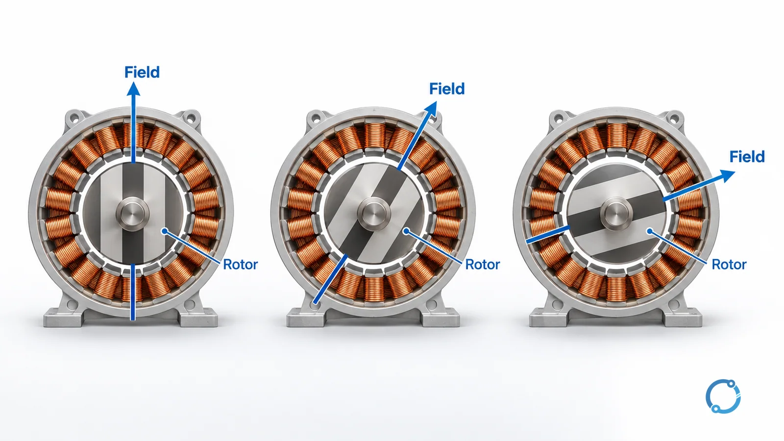
In a three-phase AC motor, winding groups occupy different positions around the stationary core. Their currents rise, fall and reverse at different times. The magnetic contribution of each group therefore changes, and the combined field moves around the circumference.
The copper windings stay still. It is the location and direction of the resultant magnetic field that rotate. This distinction explains why a motor can establish a moving magnetic pattern without any rotating electrical connection to its stator.
Supply frequency and the winding’s magnetic pole arrangement determine the field’s speed. The rotor responds to that field through the mechanism specific to its motor type. Single-phase induction motors need an additional starting arrangement to establish useful starting torque; the three-phase explanation should not be copied unchanged to every motor supplied from AC.
The DOE’s Electrical Science handbook, Volume 4 develops rotating fields and AC motor torque. The difference between changing and steady supply direction is covered separately in AC vs DC current.
The parts that make continuous rotation possible
Stator: the stationary magnetic structure
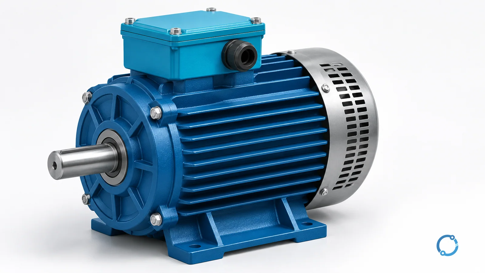
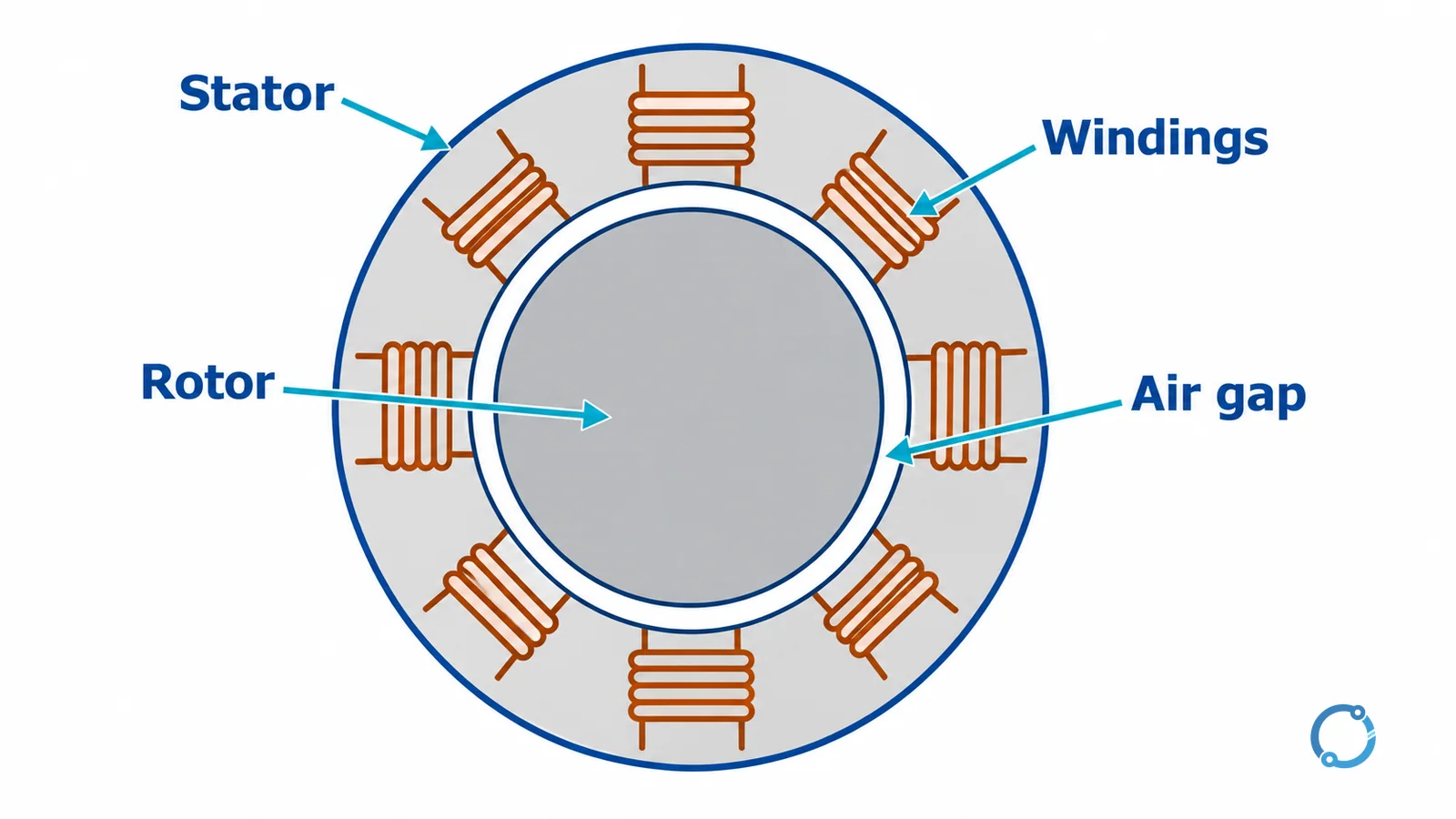
The stator is the motor’s stationary active structure. In a typical induction motor it contains a laminated magnetic core and distributed windings. Energizing those windings establishes the field that acts across the air gap toward the rotor.
The housing supports and protects this assembly, but housing and stator are not interchangeable terms. The visible outer case is the mechanical shell; the stator’s core and windings perform the electromagnetic work. Some motor families use permanent magnets for a stationary field instead of wound field poles.
Rotor: the rotating electromagnetic member
The rotor is the active part attached to the shaft. Electromagnetic torque acts on it, and the shaft carries that torque to the driven mechanism. Bearings support rotation and maintain alignment between rotor and stator.
What produces the rotor’s magnetic behavior depends on the design. It may contain cage conductors, wound coils, permanent magnets or a magnetic structure designed to align with the stator field. Calling every rotor an electromagnet fed directly from the mains would hide the key differences between motor families.
Windings: current arranged into a useful magnetic pattern
A winding is an organized set of insulated conductors. Its location, connections and current establish magnetic poles and distribute force around the machine. Copper is therefore doing more than carrying energy from a terminal to a load: its arrangement creates the motor’s magnetic geometry.
Windings can belong to the stator, rotor or both. In a brushed DC motor, the rotating armature winding receives current through a commutator. In a cage induction motor, the stator has supplied windings while the rotor’s closed conducting paths receive current by induction.
Air gap: separation with magnetic coupling
The air gap separates the stationary and rotating active parts. It allows mechanical rotation while magnetic flux crosses between them. The rotor does not need to rub against the stator to receive torque.
The gap is part of the magnetic circuit, not unused space. Its geometry influences magnetic behavior, while bearings and construction maintain the necessary mechanical separation. This conceptual explanation does not prescribe a clearance, machining tolerance or repair dimension.
Commutator and brushes: current switching in a brushed DC motor
The commutator is a segmented rotating electrical interface connected to the armature coils. Stationary brushes contact its segments and pass current between the external circuit and the rotating winding. As the rotor changes position, the connected segments change which coils receive current and in which direction.
That timed change keeps the developed torque acting in the intended rotational direction. It does not mean that the external DC supply itself alternates. Brushless designs perform electronic commutation instead, so brushes are not a defining feature of every motor marketed as DC.
Squirrel cage: an induction motor’s closed rotor circuit
A squirrel-cage rotor has conducting bars joined by end rings, forming closed current paths around a magnetic core. Relative movement between the stator field and those conductors induces rotor current. That current interacts with the magnetic field to develop torque.
The cage name describes the conducting structure, not an external protective guard. The rotor needs no brush connection to deliver its induced current. Natural Resources Canada’s electric-motor reference guide illustrates the stator, rotor and cage relationships.
How the three motor families keep turning
These categories are useful for learning, but they overlap: induction and synchronous motors are both AC motor families. The comparison here is between an AC induction motor, a conventional brushed DC motor and a synchronous motor.
AC induction: torque requires relative field motion
In ordinary induction-motor operation, the rotating stator field moves faster than the rotor. That relative movement induces current in the cage. The induced current produces the interaction that accelerates the rotor and sustains torque against the load.
Saying the field “drags” the rotor is a useful image, provided it is understood as electromagnetic interaction rather than mechanical contact. If an ideal cage rotor reached exactly the field’s speed in steady operation, relative movement would disappear and so would the induction needed to sustain load torque.
When the mechanical load changes, the rotor’s operating speed and induced-current relationship change. The difference between field speed and rotor speed is slip. It is a normal operating mechanism, not evidence by itself that the shaft coupling is slipping or the motor is defective.
Brushed DC: switch current as the rotor turns
In a brushed DC motor, armature current interacts with a magnetic field established by permanent magnets or field windings. Without appropriately timed current reversal in its coils, a simple loop would tend to reach an alignment where useful turning torque could not continue in the same way.
The commutator changes connections as the rotor passes through successive positions. Different conductors take over the torque-producing role, allowing rotation to continue while the supply remains DC. As rotation develops, the armature also generates an opposing voltage, often called back EMF, that affects current.
This is why a DC motor is more than an AC motor connected to a different supply. The internal current paths and commutation method are part of its working principle. The DOE handbook’s DC motor material explains this relationship between armature current, field and commutation.
Synchronous: rotor poles stay locked to the field
A synchronous motor’s rotor magnetic pattern rotates at the same average speed as the stator’s rotating field during synchronized operation. Rotor magnetism may come from field excitation or permanent magnets; reluctance designs achieve synchronism through their magnetic geometry.
Under load, the rotor maintains a torque-producing angular relationship to the field. Matching speed does not mean zero torque or that every magnetic axis is perfectly aligned. If the machine cannot sustain the required relationship, it may lose synchronism.
Reaching that running state still requires a suitable starting method or drive strategy. “Synchronous” describes the operating relationship, not a promise that the motor can start directly under any conditions.
Speed and torque: one calculation with clear limits
For the rotating field of an AC motor:
ns = 120f / P
Here, ns is synchronous speed in revolutions per minute (rpm), f is electrical frequency in hertz (Hz), and P is the total number of magnetic poles, not pole pairs. The factor 120 accounts for the time and pole-pair conversion.
Assume a four-pole induction motor supplied at 60 Hz. These are hypothetical teaching inputs, not a product rating:
ns = 120 x 60 / 4 = 1800 rpm
Now suppose its measured rotor speed under the stated operating condition is 1750 rpm. Slip is the speed difference expressed relative to synchronous speed:
slip = (ns - rotor speed) / ns x 100%
slip = (1800 - 1750) / 1800 x 100% = 2.78%
The denominator is 1800 rpm, not the measured 1750 rpm. The result is rounded to two decimal places and applies only to these assumed conditions. It is not a universal acceptable-slip threshold. For other cases and interpretation, use the dedicated induction-motor slip calculation guide.
Torque depends on current, magnetic flux and the motor’s electromagnetic design. Speed and torque therefore describe different aspects of operation: a shaft can turn at similar speed while delivering different torque to different loads. Voltage alone is not a complete speed command, and increasing current without considering the motor’s limits is not a general method of obtaining more useful output.
Where this explanation hands off to application guides
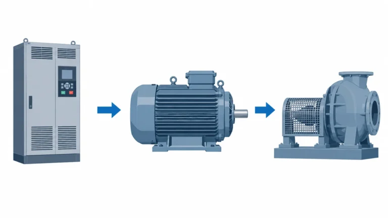
A variable frequency drive changes the motor’s electrical operating conditions; its converter stages and control are a separate subject. Choosing between controlled-motion technologies belongs in stepper vs servo motor selection, while acceleration arrangements belong in motor starting methods.
Matching the machine’s torque demand to drive capacity is covered by motor and VFD sizing for machine loads. Efficiency labels describe another property entirely, explained in IE motor efficiency classes. None of those decisions can be resolved from a diagram of the motor principle alone.
Three common misconceptions
“Voltage alone determines motor speed”
For an AC motor’s rotating field, frequency and pole count determine synchronous speed. Actual induction-motor shaft speed also depends on slip. Voltage affects the magnetic and current conditions, but changing it alone does not provide the same result as controlling frequency appropriately.
“A synchronous motor needs no starting measures”
A synchronized running state and acceleration from rest are different tasks. The motor and its supply arrangement must provide a way to reach and maintain synchronism. Zero steady running slip does not eliminate starting requirements.
“DC and AC motors differ only at the supply terminals”
Their rotor excitation, current paths and commutation can be fundamentally different. Even within AC motors, induction and synchronous designs obtain rotor torque differently. The power-source label cannot describe all those mechanisms by itself.
FAQ
How does an electric motor turn electricity into rotation?
Current and magnetic fields interact to create forces around the rotor. Those forces produce torque, and the shaft transfers that torque to a mechanical load. The motor’s winding and commutation arrangement keeps useful torque acting as the rotor turns.
What is the difference between the stator and rotor?
The stator is the stationary active structure that establishes part of the magnetic system. The rotor is the active rotating member attached to the shaft. Magnetic interaction across the air gap transfers torque without requiring contact between their active surfaces.
Why does an induction motor run below synchronous speed?
Relative motion between the rotating field and the rotor induces the rotor current needed for torque. In ordinary motoring operation the rotor therefore lags the field. That speed difference, expressed relative to synchronous speed, is called slip.
What do brushes and a commutator do?
In a conventional brushed DC motor, brushes pass current to a segmented rotating commutator. The commutator changes armature-coil connections as the rotor turns so that useful torque continues in the intended direction. Brushless motors use a different commutation arrangement.
Is 1750 rpm the synchronous speed of a four-pole motor at 60 Hz?
No. Its calculated synchronous speed is 1800 rpm. If an induction motor’s rotor speed is 1750 rpm under the assumed operating condition, its calculated slip is 2.78%. That example is not a rating or an acceptance limit for every motor.