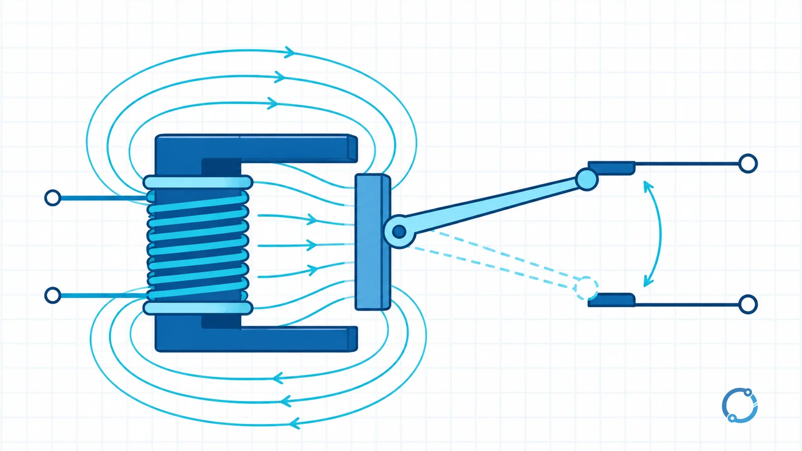
Short answer: A relay is an electrically operated switching device that uses a control signal to produce a predetermined change in one or more output circuits. In an electromechanical relay, current in a coil creates a magnetic force, an armature moves and one or more contact sets open or close. The important system idea is separation: a small control circuit can command a separate load circuit without sharing the same conductive path.
Relays appear in control panels, appliances, vehicles, buildings, communication equipment and protection systems. They can switch a lamp from a low-power control signal, create a holding or interlock circuit, isolate a logic input from a higher-voltage circuit or act as the decision element in a protective scheme. Those uses share a principle but not identical requirements.
The relay in one sentence
IEC vocabulary describes an electrical relay as a device designed to produce sudden predetermined changes in one or more electrical output circuits under defined input conditions. The definition is broad enough to include electromechanical relays, solid-state relays and protective relays.
The functional chain is:
input or control signal -> sensing or actuation -> output-circuit change
In an electromechanical elementary relay, the visible chain becomes:
coil current -> magnetic field -> armature movement -> contact change -> controlled output
The coil circuit and contact circuit can be electrically separate. That separation is the reason a relay can connect a low-voltage control switch to a higher-voltage load without bringing the load conductors onto the operator’s switch. It does not automatically provide any particular level of isolation, safety or immunity. Those properties depend on the complete component and system design.
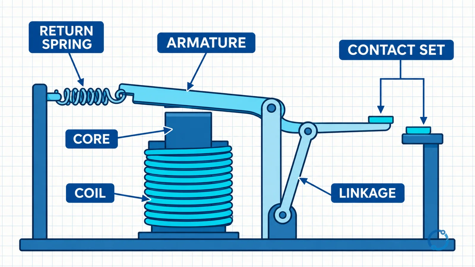
The four parts of an electromechanical relay
Coil
The coil is an electromagnetic actuator. Its winding produces a magnetic field when current passes through it. The coil has a rated voltage and an AC or DC supply type because its impedance, current and release behavior depend on the applied waveform. A coil marked for one supply type should not be assumed to work on another.
The coil is the control input, but it is still an electrical load. Its driver must supply the actual coil current and withstand turn-off.
Core and armature
The core provides a magnetic path, and the armature is the moving magnetic part. When coil flux reaches the actuation region, the armature is pulled toward the core. The movement is converted into contact displacement through a mechanical linkage or carrier.
The design may include a permanent magnet, a balanced armature or a different magnetic structure. The exact magnetic circuit belongs to the manufacturer’s design. The general principle is that electrical input energy controls a magnetic force, and that force moves the contact mechanism.
Contact set
The contacts are the output switch. A movable contact touches a fixed contact to close a path and separates from it to open the path. Contact material, spring pressure, wipe, gap and arc-control features influence electrical endurance and reliable signal transfer. A gold-plated contact intended for a low-level signal and a power contact intended for motor current are not interchangeable merely because both are called contacts.
Return spring
The spring restores the armature and contacts when the coil is de-energized. Some designs use a permanent magnet or another stored-force mechanism, but the spring is a useful elementary model because it shows that relay action is a balance between magnetic pull and mechanical restoring force.
How the relay changes state
The electromechanical sequence can be divided into four steps.
- Energize. A control voltage is applied to the coil, and coil current begins to rise.
- Actuate. Magnetic flux pulls the armature toward the core. The linkage moves the contact carrier.
- Transfer. Normally open contacts close, normally closed contacts open, and a changeover contact moves from one throw to the other.
- Reset. When coil current falls below the release level, the spring returns the armature and contacts to the de-energized state.
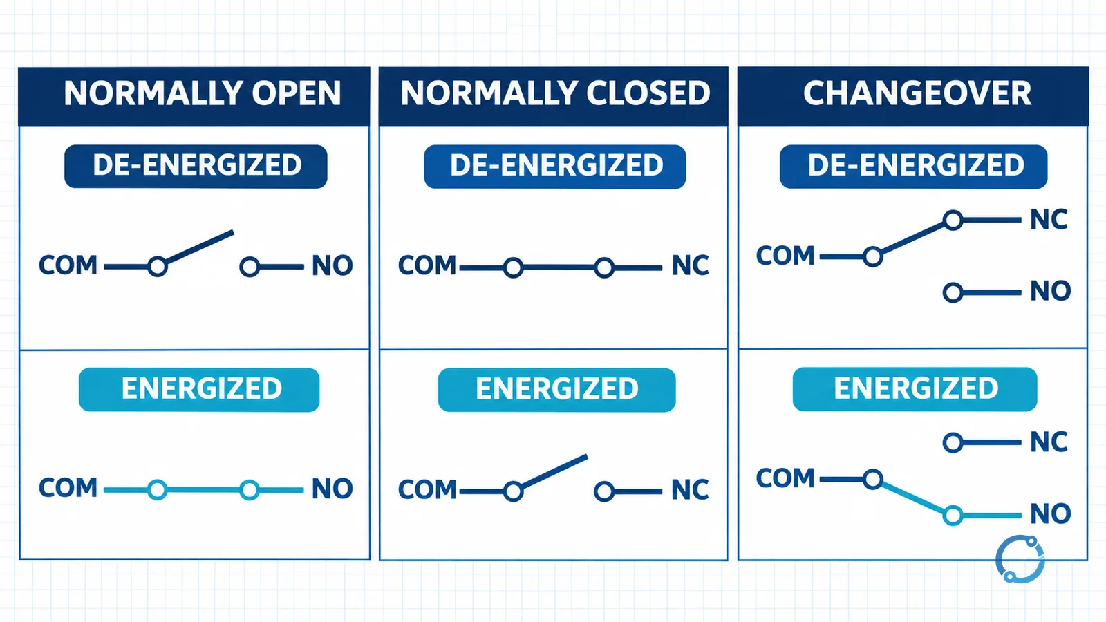
Relay terminology uses the de-energized state as the reference for normally open and normally closed. That state is sometimes called the shelf, factory or rest state, but the safest practical wording is explicit: the contact condition with the coil de-energized and no manual actuator applied.
Pickup and dropout are not necessarily identical to the nominal coil voltage. Mechanical force, temperature, magnetic history and the exact circuit affect transition. Do not infer a guaranteed switching threshold from a catalogue voltage alone.
NO, NC and changeover contacts
| Contact language | De-energized state | What happens when the relay is energized? | Common arrangement name |
|---|---|---|---|
| Normally open (NO) | Open | Closes | Form A, often SPST-NO |
| Normally closed (NC) | Closed | Opens | Form B, often SPST-NC |
| Changeover | Common connected to the NC throw | Common transfers from NC to NO | Form C, often SPDT |
The Form A, Form B and Form C labels are common in relay datasheets and control documentation. They are not the only terminology used across standards or regions, so always read the manufacturer’s terminal diagram rather than assuming that a letter code explains every internal connection.
Poles and throws
A pole is an independent contact path controlled by the same relay actuator. A throw is a contact position available to a pole. An SPST relay has one pole and one throw. An SPDT changeover has one pole and two throws. A DPDT relay has two poles, each with two throws.
This terminology gets complicated when a drawing shows a common terminal and two selectable contacts: the movable common is not counted as an extra pole, and the alternate contacts are the throws. The terminal diagram is the final authority.
Reading coil-side and contact-side specifications
The coil and contact are two different electrical systems, and their ratings should not be collapsed into one number.
Coil specifications
The coil rating identifies the intended control voltage and supply type. A hypothetical relay with a 24 V DC coil is sometimes used for teaching because it gives the reader a concrete control voltage. That does not establish a universal control voltage for relays. A real design must confirm the actual coil voltage, allowable operating range, coil resistance or power, temperature effect and driver capability from the selected device’s datasheet.
For a DC coil, the coil is inductive. Interrupting its current can produce a voltage transient at the driver unless the circuit uses a suitable suppression method. A diode can provide a path for stored inductive energy in a DC circuit, but its polarity and effect on release time matter. AC coils require a different treatment, and a suppression intended for one supply type cannot be copied blindly to the other.
Contact specifications
A contact rating describes what the contact is permitted to make, carry and break under stated conditions. The same contact may have different ratings for resistive, inductive, lamp or motor loads. AC and DC breaking behave differently because the current waveform, arc duration and available zero crossing differ.
An inductive load stores magnetic energy and can produce an arc or a voltage transient when its current is interrupted. The relay contact and the load circuit may need arc suppression, a flyback path, a snubber or a specially rated switching device. The correct method depends on the circuit and the manufacturer’s instructions; a generic capacitor or diode placed across every contact is not a universal fix.
The load calculation also has to include inrush. A filament lamp, motor, solenoid or capacitor bank can present a current or energy condition very different from its steady-state value. Never choose a relay from a single “amps” number on the front label without checking the utilization and test conditions.
Main relay types
Electromechanical relay
The electromechanical relay uses a coil, magnetic structure and moving contacts. It can provide a clear physical open gap and can switch many circuits through one actuator. Its contacts wear, bounce and produce acoustic noise, and their performance depends on the load and operating rate.
Solid-state relay
A solid-state relay uses semiconductor output devices instead of moving power contacts. It may use optical, transformer or another isolation method. No moving contact does not mean no voltage drop, leakage current or thermal limit. Some AC solid-state relays turn on near voltage zero crossing; others use random turn-on. Neither behavior proves suitability for every inductive or capacitive load.
Reed relay
A reed relay places flexible magnetic reeds inside a sealed envelope. A coil or permanent magnet makes the reeds attract and close. Reed contacts can suit low-level signals and compact isolation, but their rating and sensitivity are design-specific.
Thermal or overload relay
An overload relay responds to a condition associated with excessive thermal duty. It is not merely a general-purpose control contact. The sensing element may be a bimetal or electronic circuit, and the trip class, reset behavior and coordination belong to the motor-protection design.
Protective relay
A protective relay measures power-system quantities, applies a protection principle and commands a trip or alarm output when the defined condition is detected. Overcurrent, distance and differential protection all involve measurement and logic beyond the elementary coil-and-contact model. OHELE’s page on relay operating principles for fault detection explains definite-time, inverse-time and differential logic. A Buchholz relay troubleshooting guide addresses transformer-specific gas and oil-surge protection, while the 86 lockout trip and reset design covers lockout architecture.
The word relay therefore describes a broad functional family. Do not assume that a small control relay, an overload relay and a numerical protection relay share the same installation or testing requirements.
A power-factor relay adds another measurement-and-control example: it evaluates voltage and current information and operates output contacts according to its configured function. The power-factor relay wiring guide for LV and MV systems covers the CT, VT and control boundaries without treating the relay as a simple voltage coil.
Relay versus contactor
A contactor also uses an electromagnetic actuator to change power contacts. The difference is application and scale:
- A relay commonly handles control, interlocking, signaling or a relatively small switched load.
- A contactor is designed for frequent operation of a power circuit, often a motor or heating load.
- A protective relay measures and decides; a contactor executes switching; a circuit breaker interrupts fault current within its rating.
These boundaries overlap in real equipment. A relay can switch a contactor coil, a contactor auxiliary contact can act as a seal-in or interlock signal, and a protective relay can command a circuit breaker or contactor. The difference between a circuit breaker and a contactor explains switching duty more fully. Control-supply details for a contactor are covered in contactor selection with a 60 Hz control supply.
Where relays are used
Relays separate a control voltage from a load voltage, combine input conditions, latch an alarm after a momentary event or route a signal. In a motor circuit, a relay may energize a contactor coil, provide a seal-in path or create a start interlock. In a building panel, it may switch a fan, damper actuator or status lamp.
A relay is not a complete safety function merely because it has a normally closed contact. Emergency stopping, guard interlocking and personnel protection can require certified devices, redundancy, monitoring or hard-wired circuits. Use the applicable standards and a qualified designer.
When the relay is installed as part of a larger switchgear assembly, its control wiring must be coordinated with the switching, protection and metering functions. A relay can command a trip coil, but the trip-circuit and protective coordination requirements are not defined by the relay’s contact symbol alone.
A safe diagnostic mindset
If a relay is suspected of failing:
- Isolate the control and load circuits and verify absence of voltage at the actual terminals.
- Read the device diagram and identify coil, common, NO and NC terminals.
- Check the coil circuit and driver, then check contact continuity in the correct de-energized state.
- Inspect contact condition, terminal tightness and contamination without touching energized parts.
- Replace a damaged relay only with a compatible device and verify the complete function.
A simple continuity reading in the wrong state can create a false diagnosis because a changeover contact is expected to be connected to one terminal while de-energized and another terminal while energized. The fundamentals of voltage and resistance help interpret the readings, but isolation and energized-work boundaries are non-negotiable.
Common mistakes
Treating the relay as a single-rating device
The coil voltage, contact current, load type and operating duty are separate specifications. A particular coil supply does not make every contact load suitable.
Assuming NO and NC are active or inactive
NO means open when de-energized; NC means closed when de-energized. The meaning reverses for some control schemes if the de-energized state is not what the designer intended, so draw the state on the schematic.
Using a control relay as a motor contactor
The actuating principle may look similar, but a contactor’s power contacts, utilization rating, arc control and endurance are selected for power-circuit duty.
Omitting suppression or arc control
Inductive loads and coils store energy. A contact or driver can see voltage transients and arcing. Use the manufacturer’s protection method and verify that it does not delay release or create an unintended path.
FAQ
What is a relay used for?
A relay is used to control one electrical circuit with a separate control signal. It can isolate a low-power input from a switched load, combine logic conditions, latch an alarm or command a contactor, breaker or protective function.
What is the difference between a normally open and normally closed relay contact?
A normally open contact is open when the relay is de-energized and closes when actuated. A normally closed contact is closed when de-energized and opens when actuated. The de-energized state must be explicitly identified in the schematic.
What does SPDT mean on a relay?
SPDT means single-pole, double-throw. It has one common contact and two selectable throws, typically a normally closed contact and a normally open contact. It is commonly called a changeover contact or Form C arrangement.
Is a solid-state relay just a relay with no moving contacts?
The functional purpose is similar, but the isolation method, output device, voltage drop, leakage current, turn-on behavior and thermal design differ from an electromechanical relay. The load and switching conditions still have to be verified.
Is a relay the same as a contactor?
They share an electromagnetic switching principle, but a contactor is generally built for power-circuit switching and frequent operation, while a relay often handles control or lower-power switching. The boundary depends on the product’s tested ratings and the application.
Sources
- International Electrotechnical Commission. IEC 60050-444: International Electrotechnical Vocabulary – Part 444: Elementary relays. The catalogue page is used for standard identity and public scope.
- International Electrotechnical Commission. IEC 61810-1: Electromechanical elementary relays – Part 1: General and safety requirements. The catalogue page is used for standard identity and public scope; the full licensed text was not accessed.