Short answer
A generator converts mechanical energy into electrical energy. A prime mover turns a rotor, the rotor establishes a magnetic field, and that moving field induces voltage in stationary stator conductors. In the common synchronous generator used for large-scale power production, direct current (DC) excitation creates the rotor field while the stator delivers alternating current (AC) to the load.
The machine therefore does two jobs at the same time. It provides a magnetic field strong enough to induce voltage, and it maintains relative motion between that field and the stator winding. Frequency follows rotor speed and pole count; terminal voltage is regulated mainly through excitation. These two control paths explain much of what a generator does in service. For a broader view of where generation sits in the power system, see how electricity is generated.
The energy-conversion chain
The word “generator” can suggest that the machine manufactures electrons. It does not. Conductors already contain mobile charge carriers. An induced electromotive force (EMF) gives those charges a voltage reference and drives current when a complete circuit is connected. The generator changes the form of energy supplied by the prime mover into electric energy delivered at its terminals.
The sequence is:
- The prime mover supplies torque.
- The rotor turns through the machine’s magnetic field.
- The changing flux linkage induces EMF in the stator winding.
- A connected load draws current, producing an opposing electromagnetic torque.
The last step matters. A generator produces no useful electric power in isolation merely because it is spinning. Load current creates a magnetic field of its own, and the interaction between rotor and stator fields opposes rotation. The prime mover must therefore supply more mechanical power as electrical output rises. This is one practical expression of energy conservation.
Rotor, stator, prime mover and excitation
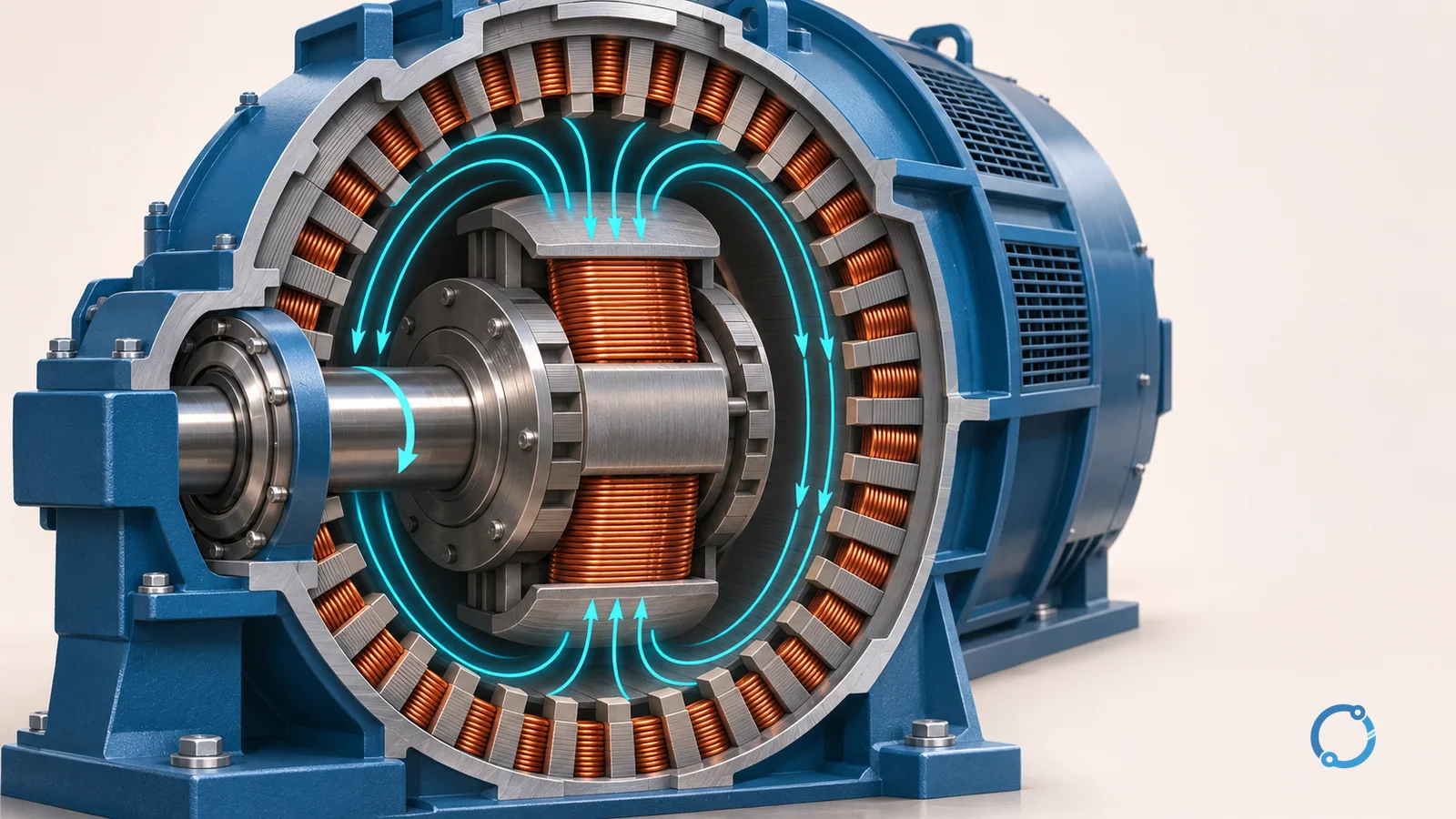
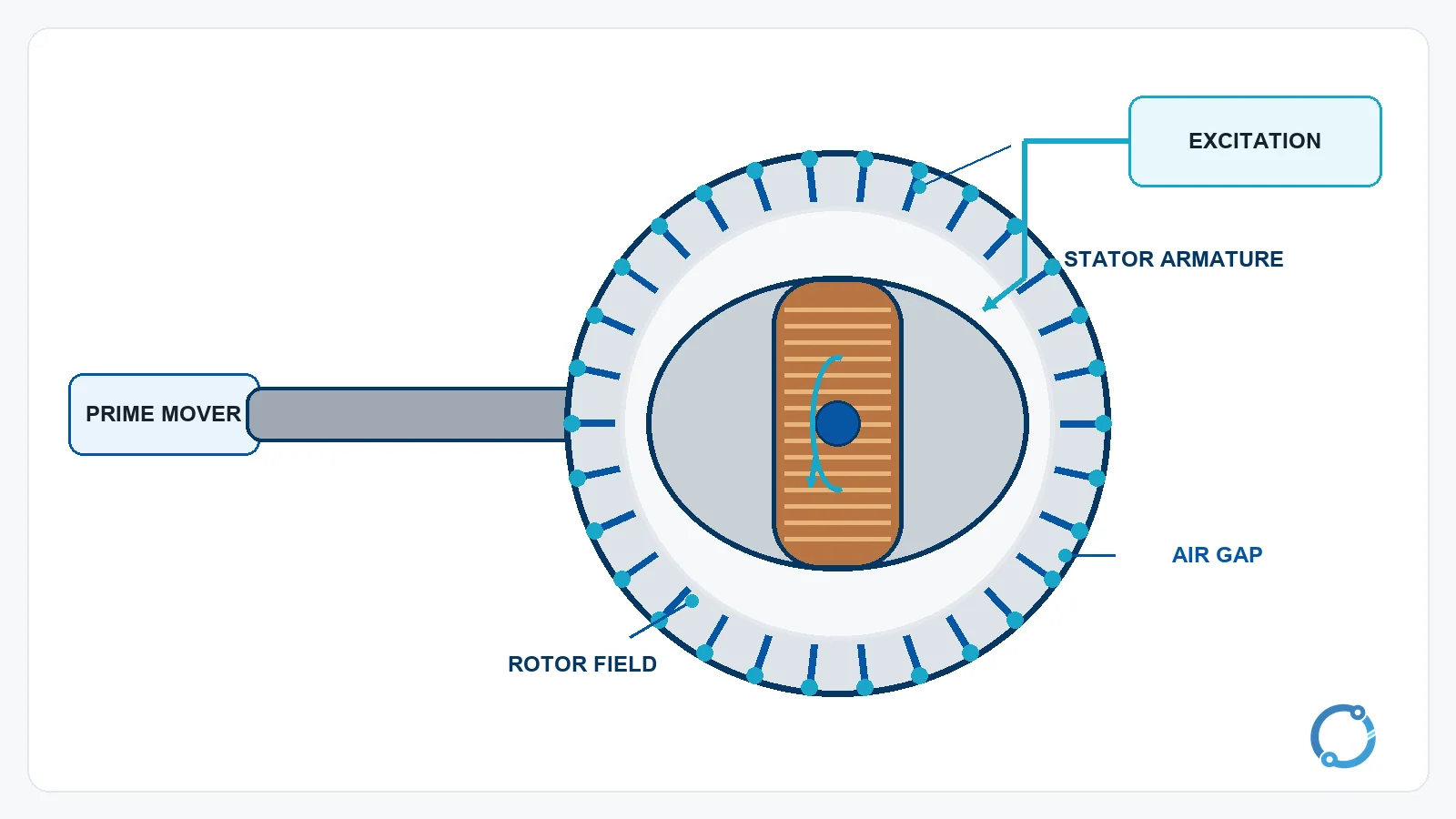
The conventional synchronous generator has a rotor, a stator, a field winding or permanent-magnet field, and an excitation arrangement. The rotor is the rotating member. The stator is stationary and surrounds the rotor across an air gap. In the usual large synchronous machine, the rotor carries the DC field and the stator carries the armature winding that produces the AC output. Some generators use the opposite arrangement, with a rotating armature and a stationary field. The functional idea remains similar, but the construction has different slip-ring and maintenance implications.
The prime mover is the machine that turns the shaft. It can be an engine, steam turbine, gas turbine, water turbine or another driver. The electrical article should not confuse the prime mover with the generator itself. A diesel engine and a steam turbine can both drive synchronous generators, but the reasons for their selection belong to the energy source and plant design. The generator converts the resulting shaft power; it does not decide where that power came from.
The excitation system supplies the field. In a separately excited machine, DC current flows through a field winding to create magnetic flux. An exciter can be a separate machine, a static rectifier arrangement or another controlled source. A permanent-magnet generator replaces the wound field with permanent magnets, so its field is not controlled in the same way.
The automatic voltage regulator, or AVR, controls excitation current in response to measured terminal voltage. It does not directly set rotor speed. The speed governor and prime mover mainly determine frequency in an isolated system, while the AVR mainly influences voltage. In a large interconnected grid, the relationships become more complex because other generators and control systems also act on system frequency and voltage.
How the magnetic field produces voltage
Faraday’s law describes the central effect: an EMF is induced when the magnetic flux linking a conductor changes. In a rotating machine, the rotor field continuously moves relative to the stator winding. Each stator conductor therefore experiences a changing flux as field poles pass it. The resulting EMF reverses as the magnetic polarity alternates.
This is why a generator can produce AC without a separate oscillator. As the north and south field poles sweep past a given stator coil, the induced voltage reverses direction each time the polarity reverses. A complete rotation produces one cycle for a two-pole machine and a different number of electrical cycles for machines with more poles. The winding arrangement shapes the waveform, distributes the voltage and reduces unwanted harmonic content.
The sinusoidal induced-EMF equation often used for a phase winding is:
E = 4.44 x f x N x Phi x Kw
In this expression, E is the root-mean-square induced EMF per phase, f is frequency in hertz, N is the number of series turns per phase, Phi is the peak magnetic flux per pole in webers and Kw is the winding factor. The 4.44 factor is the familiar result for a sinusoidal flux distribution. It is not a universal constant for every waveform or every machine model. Real design calculations account for saturation, winding layout, armature reaction and losses.
No numeric turns or flux example is needed to understand the relationship. A stronger field, more effective series turns, higher frequency or a larger useful flux can increase the induced EMF, but those variables are bounded by the actual magnetic and thermal design. The formula explains direction and dependence; it does not authorize a field-winding value for an unknown machine.
Why the output is AC
The rotor field does not brush past one fixed conductor with one fixed polarity. Its north and south regions alternate as the shaft rotates. The stator therefore sees a periodically changing flux linkage, and the induced EMF alternates in polarity. That is alternating current in its most basic machine-level form.
A DC generator uses a commutator to switch the connection between the rotating armature and the external circuit so the output remains unidirectional. An AC generator does not need that reversal-suppression function. Its output may be taken through fixed stator terminals in a rotating-field machine, or through slip rings in a rotating-armature machine. For a comparison of the two supply forms and why transmission systems use AC, see AC vs DC current.
The distinction is not just a naming preference. AC permits the output to pass through a transformer, which can change voltage with a magnetic circuit rather than a continuous electronic conversion stage. That is one reason large power systems use AC generation and transformation together. A transformer itself does not change frequency; it changes voltage and current according to its turns ratio. The relationship is explained in how a transformer works.
Frequency: speed, poles and the 120 factor
The synchronous frequency of an AC generator is:
f = P x N / 120
Here P is the total number of poles and N is rotor speed in revolutions per minute. The factor 120 combines the conversion from minutes to seconds with the fact that a pole pair is required for one complete electrical cycle.
For a four-pole machine:
- At 1,500 rpm:
f = 4 x 1,500 / 120 = 50 Hz. - At 1,800 rpm:
f = 4 x 1,800 / 120 = 60 Hz.
The result is a direct relationship at fixed pole count. If speed falls by 3 percent, synchronous frequency falls by 3 percent. If speed rises, frequency rises in the same proportion. This is why governor behavior is central to isolated generator frequency control.
The calculation gives synchronous frequency. It does not mean every generator will operate at either 50 Hz or 60 Hz regardless of design. Those are common system frequencies, but an actual machine must be selected and operated for its rated frequency, speed, pole count and application. A four-pole machine at another speed produces another frequency.
Voltage: excitation and the AVR loop
At a given speed, increasing field current increases magnetic flux and tends to increase terminal voltage. Reducing field current has the opposite effect. This gives the excitation system a direct voltage-control lever.
The AVR forms a closed loop:
- Measure terminal voltage.
- Compare it with the desired reference.
- Adjust excitation current.
- Observe the resulting voltage and repeat.
When load increases, armature current creates its own magnetic effect and terminal voltage tends to change. The AVR responds by adjusting field current within the machine’s capability. It cannot make an overloaded or undersized generator deliver unlimited current, and it cannot correct a mechanical-speed problem by itself. Excitation control, prime-mover control and protection must work together.
Excitation also has limits. A field winding has a maximum continuous current and insulation temperature, and the magnetic circuit can saturate. A control loop that demands more field current than the machine can safely provide is not a substitute for correct rating and protection. The manufacturer’s machine data, capability curve and protection settings define the operating envelope.
Why three phases appear together
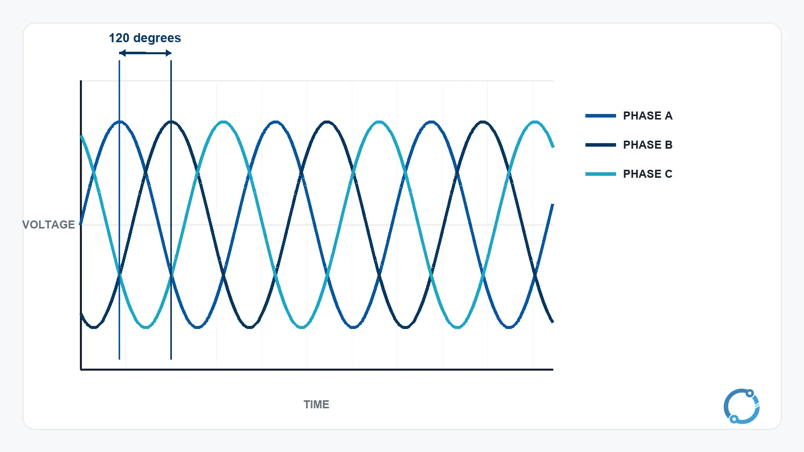
A three-phase generator uses three stator winding sets arranged so their output voltages are displaced by 120 electrical degrees. With a balanced load and a symmetrical winding, the three voltages have equal magnitude and a fixed phase relationship. The instantaneous sum of the three phase voltages in a balanced system is zero, which is why a three-wire balanced load can operate without a neutral return for the fundamental component.
The three-phase arrangement gives a smoother power transfer than a single-phase machine of comparable size. It also provides a rotating magnetic field when the phases are applied to a motor, and it allows transformers and transmission equipment to handle power with a consistent phase relationship. The machine principle is the same as the single-phase case; the winding layout and system connection change.
What happens when load is connected
With no load, the generator still has field excitation and induced voltage, but the stator current is essentially limited to losses and excitation-related effects. When a load is connected, current flows in the armature winding. That current produces an armature magnetic field. The interaction between the armature field and the rotor field is called armature reaction.
Armature reaction affects both voltage and the magnetic conditions inside the machine. It can strengthen or weaken the effective field depending on the load power factor, and it can shift the rotor’s electrical position relative to the terminal voltage. The AVR reacts to the resulting voltage change, while the prime mover responds to the additional torque demand. A generator therefore has coupled electrical and mechanical behavior, not an isolated voltage source with unlimited reserve.
In a synchronous machine connected to a large network, the rotor runs at synchronous speed and its load angle changes with power transfer. If the machine is driven beyond its stability boundary, it can lose synchronism. That condition is not a normal operating mode and requires protection and control. The generator paralleling and synchronizing checks page covers the connection conditions and practical checks that belong to that task.
The generator’s output current also becomes a system fault-study input. The machine, its excitation system and the network determine how much current is available during a short circuit. The generator circuit-breaker breaking-capacity guide explains why the breaker must be evaluated against the source’s fault contribution rather than against the generator’s normal load current alone.
Generator types in one view
Synchronous generators are the standard choice for large AC power generation because their rotor can remain locked to the rotating stator field at synchronous speed. An induction generator is different: it needs a source of magnetizing reactive power and operates with slip relative to synchronous speed. A permanent-magnet generator uses magnets instead of a wound rotor field, which removes one excitation path but introduces its own control and fault-current considerations.
Excitation can be brushed or brushless. A brushed system may use slip rings to transfer field power to the rotor; a brushless exciter uses a rotating rectifier arrangement. The choice affects maintenance, control and protection, but no single arrangement is universally best. The machine’s application, environment, control requirements and service support decide the tradeoff.
The prime mover is a separate layer. A diesel engine, gas turbine, steam turbine and water turbine all turn a generator, but they have different speed control, starting, fuel and dynamic characteristics. A generator article should keep that distinction clear. The how electricity is generated overview explains the wider energy-conversion routes.
Generator and motor: one principle, two directions
A motor converts electric energy into mechanical work; a generator converts mechanical work into electric energy. Both depend on the interaction of current-carrying conductors and magnetic fields. In fact, a synchronous machine can operate in either direction under the right excitation and prime-mover conditions.
The comparison is useful because it corrects the idea that motors and generators are unrelated devices. They share the same magnetic circuit, windings and machine physics. The operating direction, control system and protection philosophy change, but the underlying torque and induction relationships remain linked. For the motor-side explanation, see how an electric motor works.
Ratings and the information a generator actually needs
Generator ratings are not just one current number. A machine has a voltage, frequency, speed, phase count, apparent-power rating and a specified power factor. The kW capability is also tied to the prime mover and the machine’s thermal limits. A generator nameplate can look simple, yet the permissible operating area depends on cooling, ambient conditions, excitation and load profile.
That is why a generator sizing question should not be answered by matching a single load kW value to a catalog number. Starting current, motor loads, power factor, step loading, altitude, ambient temperature and the type of prime mover can all alter the required machine. The standby generator sizing guide covers the load-step approach in more detail. Current itself is the rate of charge flow described in what is electric current, while the generator’s voltage and current together determine the apparent power delivered.
Safety boundary
Generators can create hazardous voltages and can backfeed a circuit during an outage. Installation, paralleling, neutral arrangement, grounding and protection must follow the applicable electrical code and the manufacturer’s instructions. A generator that is not correctly isolated can energize a conductor that maintenance staff expect to be dead.
Testing, synchronizing and fault-current work belong to qualified persons using the site’s switching and safety procedures. This article explains the machine principle; it does not provide a connection design or authorize work on an energized generator.
Frequently asked questions
Does a generator create electrons?
No. It creates an EMF that drives charge carriers already present in the circuit. The machine converts mechanical energy into electric energy; it does not manufacture the charge itself.
Why does generator frequency depend on rotor speed?
The rotor field moves past the stator winding once per mechanical revolution for each pole-pair cycle. With a fixed pole count, faster rotation produces more electrical cycles per second. That is why frequency and speed are directly related for a synchronous generator.
Does increasing excitation increase frequency?
Excitation mainly controls voltage by changing the magnetic field. Frequency in an isolated system is primarily tied to rotor speed and pole count. In an interconnected system, frequency is a shared system variable, so the simple statement needs the system context.
What is the difference between a generator and an alternator?
“Alternator” is commonly used for an AC generator. The term emphasizes that the output alternates. It is not a promise of a particular construction, excitation method or application.
Can a generator run without a prime mover?
No. A generator needs relative motion between its field and armature. The prime mover supplies that motion and the torque required to meet the electrical load. Without a prime mover, the machine has no sustained mechanical-energy input.