
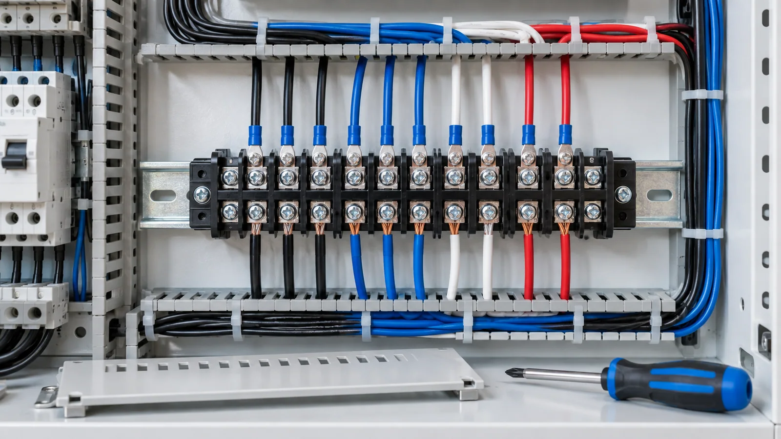
Install a barrier terminal block only after confirming the circuit ratings, accepted conductor and lug types, required spacing, enclosure conditions, hardware stack, strip length and tightening torque from the exact product documentation. De-energize and isolate the circuit, verify absence of voltage, preserve every barrier and cover, prepare conductors without damage, tighten with a controlled tool, then complete independent visual and electrical checks before energization.
This workflow addresses fixed low-voltage panel and equipment wiring by qualified personnel. It does not authorize energized work or provide universal torque, strip-length or spacing values.
What a barrier terminal block is—and is not
A barrier terminal block uses insulating walls between adjacent poles to reduce accidental contact and help maintain separation. Depending on the design, it may accept ring/fork lugs, bare conductors under a pressure plate, or another specified termination.
The barriers do not automatically establish adequate clearance or creepage for every voltage, pollution degree or enclosure. Nor do they provide overcurrent protection, disconnecting, touch-safe construction or conductor strain relief unless the selected assembly is designed and documented for those functions.
IEC 60947-7-1:2025 covers industrial terminal blocks with screw-type or screwless clamping units for copper conductors within its scope. A product’s compliance must be established from its own documentation; the existence of the standard is not proof that an unmarked block complies.
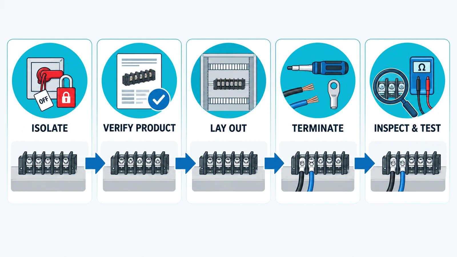
Hold-point plan
| Hold point | Evidence required | Stop condition |
|---|---|---|
| product selection | part number, ratings, conductor/lug range, standard/listing evidence | missing or mismatched data |
| panel layout | spacing, cover, access, heat and wire-bend review | barrier/cover removed or spacing compromised |
| conductor preparation | correct size/class, strip length or crimp record | nicked wire, cut/stray strands, wrong lug/ferrule |
| mechanical assembly | correct screws/washers/jumpers and calibrated torque tool | mixed hardware or no product torque value |
| inspection/test | visual, continuity, grounding and project-required tests | unexplained resistance, heat damage or wiring discrepancy |
Stage 1: establish a safe work condition
Only qualified or authorized personnel should install or service terminal blocks. Follow the site and jurisdiction’s energy-control rules. In U.S. general-industry servicing, OSHA 29 CFR 1910.147 requires an energy-control program and verification of isolation within its scope.
Before work:
- identify all normal, alternate and backfeed sources;
- shut down using the approved procedure;
- isolate and apply lockout/tagout;
- release or control stored energy;
- verify de-energization with an approved test method;
- protect against adjacent live parts as required;
- confirm the drawing and terminal schedule revision.
If the circuit cannot be made safe under the approved procedure, stop. A small terminal block does not make live work low risk.
Stage 2: verify the terminal against the circuit
Check the exact catalog/datasheet and certification record for:
- rated voltage and current in the applicable use;
- accepted copper-conductor sizes and classes;
- bare-wire, ring-lug, fork-lug or ferrule acceptance;
- one or multiple conductors per position;
- terminal screw and mounting screw specifications;
- required torque and tool;
- strip length or lug dimensions;
- jumper, marker, cover and end-plate compatibility;
- operating temperature and material limits;
- mounting method and panel thickness;
- applicable IEC, UL or national evidence;
- short-circuit or control-circuit application requirements.
For U.S. industrial control panels, use the component’s actual UL category/conditions and the panel standard. UL’s 508A Supplement SA resource supports component selection; it does not make every barrier strip acceptable in every panel.
Stage 3: lay out the block and wiring
Place the block so technicians can see markings, operate screws with the correct tool and inspect connections. Verify:
- required separation from other live parts and grounded metal;
- space for the insulating cover and end barriers;
- conductor bend radius and routing channels;
- separation of power, control and sensitive signal wiring where the design requires it;
- heat sources and ventilation;
- environmental exposure, contamination and condensation;
- access for test probes only where designed;
- secure mounting without twisting the base;
- labels visible after wiring.
Do not cut away barriers to fit an oversized lug. Do not omit a cover because the conductor is difficult to route. Change the terminal, lug, position or enclosure layout.
Stage 4: prepare conductors and terminals
The solid-versus-stranded terminal-block guide explains conductor-class choices in detail. For the installation at hand:
Bare conductor
- strip only to the manufacturer’s dimension;
- use a stripping tool that does not nick the conductor;
- keep all strands together;
- do not trap insulation in the clamping area;
- do not leave excess exposed copper.
Crimped ring or fork lug
- match lug material, barrel and stud/fork dimensions to the conductor and terminal;
- use the specified crimp die and controlled tool;
- confirm full conductor insertion and correct crimp location;
- inspect for cracks, loose strands or damaged insulation;
- use heat-shrink/insulation support only as specified;
- orient the lug so tightening does not force it out of the barrier or against another pole.
Ferrule
Use a ferrule only if the terminal accepts it. Size it to the conductor and use the approved crimp profile. A ferrule that fits into the opening is not necessarily an approved combination.
IEC 60999-1:1999 addresses screw-type and screwless clamping units for rigid and flexible copper conductors within its scope. Product instructions still control the preparation method.
Stage 5: mount and assemble the hardware
Clean the mounting surface and install the block without distortion. For stud or screw-lug designs, reproduce the specified hardware sequence exactly. Depending on the product, this may include a terminal screw, lug, flat washer, spring element or captive hardware—but no universal stack applies.
Rules that prevent common defects:
- never substitute a screw with different length, thread or head geometry;
- do not place a washer where it reduces barrier clearance;
- do not stack lugs unless the terminal is rated and documented for it;
- use only matching jumpers and covers;
- do not use the terminal screw to pull a misaligned conductor into position;
- support heavy cables so their weight does not rotate the lug or block;
- preserve phase/polarity and terminal numbering throughout assembly.
Stage 6: tighten to the documented value
Use the product-specific torque with the specified tool. Record the value and tool identification where the quality plan requires it.
There is no safe generic torque table for all barrier blocks. Torque depends on thread, material, pressure system, conductor/lug and certification conditions. Undertightening can raise contact resistance; overtightening can damage threads, crack the base, deform lugs or reduce insulation spacing.
Use a controlled sequence when multiple lugs or jumpers share an assembly. Paint witness marks may show later movement, but they do not prove that the original torque was correct and should not bridge insulation surfaces unless approved.
Stage 7: inspect before electrical testing
Use an independent second-person check for critical circuits. Verify:
- part number and terminal schedule match;
- barriers, end plates and covers are complete;
- conductors and lugs are within the accepted range;
- no nicked, cut or stray strands;
- no insulation trapped under a current-carrying clamp;
- no excess exposed conductor;
- lugs sit flat and do not bridge adjacent poles;
- jumpers match the drawing;
- torque record is complete;
- labels, polarity and phase are correct;
- harnesses are supported and not pulling on terminals;
- mounting screws and terminal screws have not been confused.
Stage 8: perform approved verification tests
IEC 60364-6:2016 provides requirements for initial and periodic verification of low-voltage installations. Apply the project and jurisdiction’s required sequence, which may include:
- protective-conductor continuity;
- circuit continuity and point-to-point checks;
- insulation resistance after sensitive equipment is isolated as required;
- polarity and phase identification;
- functional checks of connected circuits;
- comparison against drawings and terminal schedules;
- low-resistance measurement for selected high-current joints where specified;
- thermal inspection after controlled operation, when included in the maintenance plan.
Do not megger through connected electronics or surge protective devices unless the approved test plan permits it. A continuity beep alone cannot establish connection quality or current rating.
Defects and likely causes
| Defect | Possible cause | Safe response |
|---|---|---|
| heat discoloration or melted barrier | loose/high-resistance joint, overload, wrong lug, poor contact | isolate, investigate circuit and replace damaged parts |
| cracked base | overtorque, uneven mounting, impact or incompatible hardware | replace block and correct mounting/tool control |
| lug rotates during tightening | unsupported conductor, wrong hardware or poor access | remake routing and assemble per instructions |
| adjacent-pole flash marks | lost barrier/cover, contamination, inadequate spacing or overvoltage | remove from service and complete engineering investigation |
| conductor pullout | wrong size/preparation or incomplete clamp | reselect/reterminate and inspect similar points |
| intermittent control signal | loose connection, broken strands, vibration or wrong jumper | isolate, test point-to-point and correct root cause |
Do not restore a heat-damaged terminal by tightening it. Heat can anneal conductors, relax spring parts and carbonize insulation; replace and investigate according to the equipment procedure.
Installation record
Capture:
- panel/equipment and terminal-block identification;
- manufacturer, part number and rating data;
- conductor and lug/ferrule details;
- drawing and terminal schedule revision;
- torque value source, tool ID and calibration status;
- installer and checker;
- continuity/insulation/functional results as applicable;
- deviations and approved dispositions;
- date and final cover/label inspection.
If the design decision is still between connector families, use the terminal blocks versus wire connectors comparison before applying this installation workflow.