
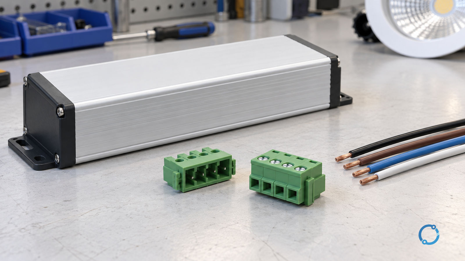
A matched pluggable terminal interface can make an LED driver easier to replace without repeatedly disturbing every field-wire termination. The benefit exists only when the connector, driver, LED load and service procedure are compatible. “Pluggable” does not mean touch-safe in every state, suitable for load breaking or safe to unplug while energised.
This guide is for designing and reviewing serviceable luminaire or lighting-system interfaces. It is not a live maintenance tutorial, a driver-repair guide or an endorsement of a connector family. A designation such as “2EDGK” is not an electrical standard or evidence that two manufacturers’ parts interchange. Use the exact mating-part identification and verified documentation instead.
Treat the driver as several different interfaces
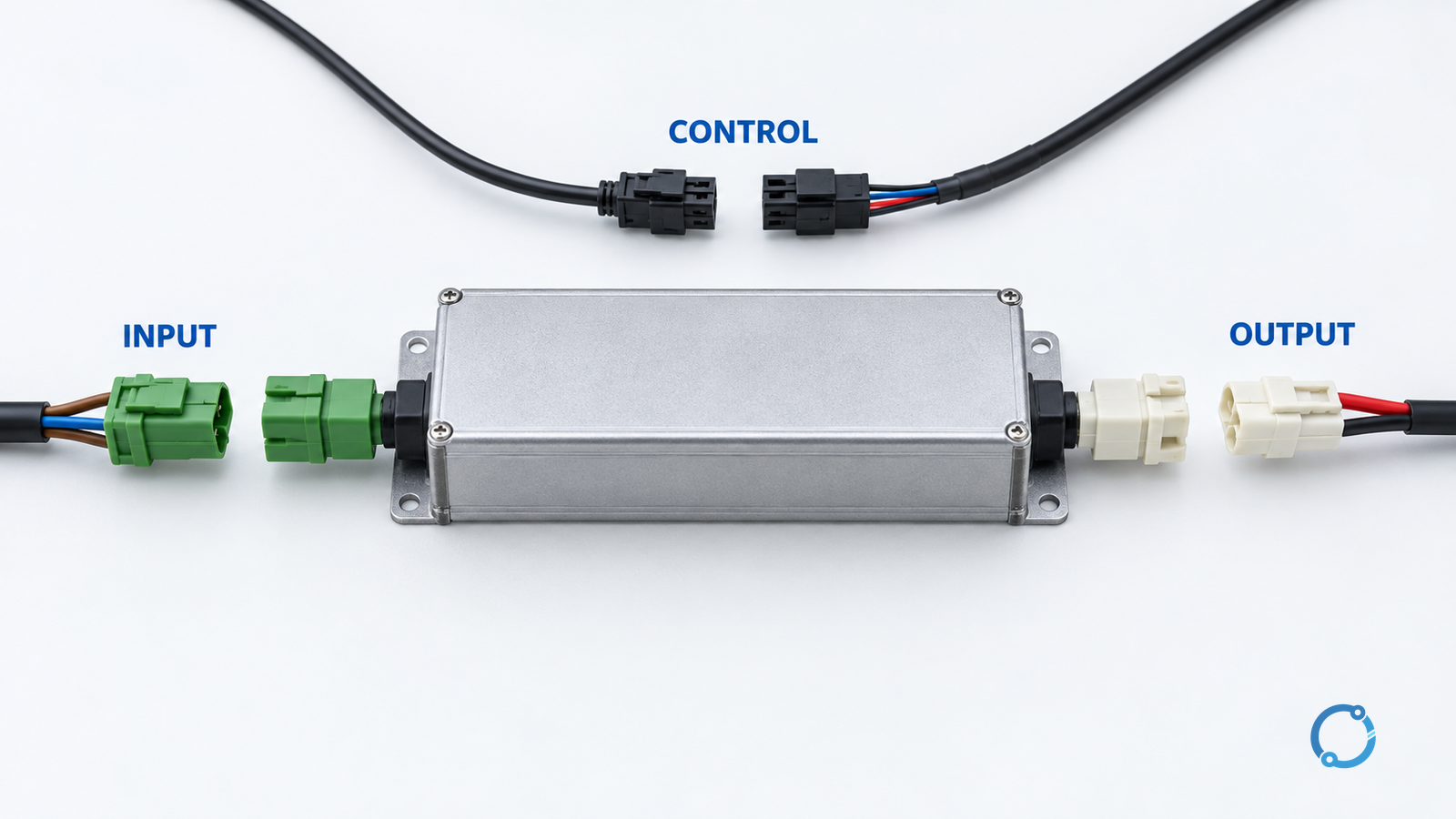
The mains input, LED output and control interface have different duties. Depending on construction, protective bonding may introduce another required connection. Do not transfer an input connector’s suitability to the output or assume that a small output connector carries a harmless voltage.
IEC 61347-2-13:2024 addresses safety requirements for electronic controlgear for LED light sources. Its scope does not establish compatibility between an arbitrary replacement driver and a luminaire. The driver and complete equipment documentation remain essential.
| Interface | Replacement evidence | Stop condition |
|---|---|---|
| Supply input | Supply type/range, terminals, insulation and connector application | Unknown supply requirement or mismatched mating pair |
| LED output | Constant-current or constant-voltage mode, permitted load range, output limits and polarity | Same wattage but incompatible electrical output |
| Control/dimming | Actual protocol, reference arrangement and permitted wiring | Similar connector shape but incompatible control function |
| Protective bonding, where required | Equipment protection class and approved bonding arrangement | Continuity would depend on an unverified service connection |
The terminal-marking guide explains why markings need a defined meaning. A pitch, colour or number of ways is not a complete interface specification.
Step 1: define the approved connector pair
Record both halves, orientation, terminal numbering, locking features, wire-entry direction and accessible contact state when unmated. Check voltage/current suitability under the declared conditions, permitted conductor sizes, wire preparation, temperature limits and any insertion-cycle or handling restrictions relevant to service.
Do not qualify a pair by forcing it together. Mechanically similar housings can have different keying, tolerances or contact geometry. A retaining feature must suit the installation’s vibration, cable pull and access conditions; the cable should not become the handle for removing a plug.
IEC 61984:2008 provides connector safety requirements and tests within its stated scope. Whether a particular connector is permitted to make or break its circuit under load requires its actual declaration. For this maintenance workflow, plan isolation before separation rather than assuming load-breaking capability.
Step 2: make replacement compatibility explicit
Create an approved replacement record for the driver, not merely the connector. Include input requirements, output operating mode and range, LED-load compatibility, dimming behaviour, enclosure/thermal requirements and mechanical mounting. A constant-current driver and a constant-voltage driver are not interchangeable simply because their nominal power is similar.
Specify a harness map that keeps different functions distinguishable. Keying and unambiguous identification can reduce wrong reconnection; colour alone should not carry the whole safeguard. Review whether a technician can inadvertently exchange two physically identical plugs. If so, correct the interface design or procedure before release.
Step 3: plan isolation and access
Identify all energy sources and any stored energy before opening equipment. Control inputs, emergency-lighting arrangements or other auxiliary sources may need separate treatment. A switch command or dimming instruction is not evidence that the equipment is electrically isolated.
In covered US workplaces, OSHA 1910.333 addresses de-energising, stored energy and verification before treating parts as de-energised. Elsewhere, follow the applicable rules and site procedure. Qualified personnel must establish a safe state; there is no universal wait time in this article.
If isolation cannot be verified, documentation is missing or accessible damage is found, stop. Do not use the connector’s convenience to bypass the safe-work process.
Step 4: replace without changing the interface contract
Under the approved isolated procedure, inspect the accessible connector and harness condition. Cracked insulation, heat damage, loose wire preparation or a distorted latch requires resolution, not reuse by default. Where conductor retermination is necessary, use the actual terminal instructions rather than a universal torque or strip length.
Support the plug housing and release its retaining mechanism as instructed. Do not pull on the wires. Install the approved driver and reconnect only the verified matched interfaces in their documented positions. Check full seating, retention, cable strain relief and any required bonding continuity before closing the equipment.
For the separate task of replacing a damaged terminal rather than the driver assembly, use the terminal-block replacement checklist.
Step 5: verify and release
The final check should establish that the intended driver/load/control combination is restored, connections are correctly seated, covers and protection features are reinstated, and required electrical and functional verification has been completed under the applicable procedure. A lamp lighting up is not proof of every safety or thermal requirement.
Retain the as-left driver identity, connector-pair identity, harness map, inspection findings and verification record. The serviceable design succeeds when the next replacement is repeatable and bounded—not merely faster to unplug.