
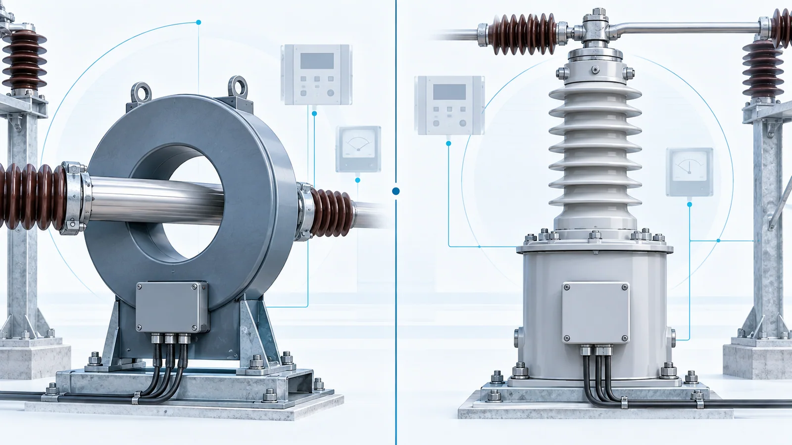
Current transformer (CT) and voltage transformer (VT) selection begins with the connected function: revenue metering, indication, protection, control, disturbance recording, or a combination. From there, match system voltage and insulation, primary ratio, secondary interface, accuracy class, burden, frequency, fault duty, transient behavior, environmental conditions, and the requirements of every connected device.
The most common selection error is to choose only a ratio. A ratio can look correct while the complete measurement chain saturates, exceeds its burden, lacks the required insulation or short-time capability, or performs poorly over the actual current and voltage range.
Safety boundary
Instrument transformers interface high-energy primary systems with secondary circuits that may also become hazardous under abnormal or incorrect conditions. Selection, installation, grounding, testing, and commissioning require qualified personnel and a design based on the applicable standard, system study, protection philosophy, and local rules.
A conventional CT secondary must not be casually opened while primary current is flowing; a hazardous secondary voltage and loss of measurement can result. VT secondary circuits require correctly engineered protection against faults and inadvertent backfeed. Treat secondary grounding and isolation as design features, not field improvisations.
Start with the standards framework
The applicable document depends on technology, voltage class, signal type, jurisdiction, and project specification.
- IEC 61869-1:2023 provides general requirements for instrument transformers within its stated scope and directs users to the relevant product-specific parts.
- IEC 61869-2:2012 adds requirements for inductive current transformers used with measuring instruments and protective devices.
- IEC 61869-3:2011 covers inductive voltage transformers for measurement and protection within its scope.
- IEEE C57.13-2016 addresses performance and interchangeability requirements for current and inductively coupled voltage transformers used in AC power systems, including metering accuracy classes and test requirements.
Do not mix IEC and IEEE class markings as though they were interchangeable. Select and verify against the project-specified system, edition, and connected-device requirements.
A selection path that prevents late redesign
Use one data sheet for the complete measuring chain:
- Define each measuring and protection function.
- Establish primary system conditions and insulation requirements.
- Select the ratio and usable operating range.
- Calculate the connected burden, including leads and terminals.
- Select accuracy and performance class for the actual function.
- Verify CT fault-current and transient performance or VT voltage-factor and transient needs.
- Define secondary rating, grounding, protection, test facilities, and terminal arrangement.
- Verify compatibility with meters, relays, recorders, and merging units.
- Document test and commissioning acceptance criteria.
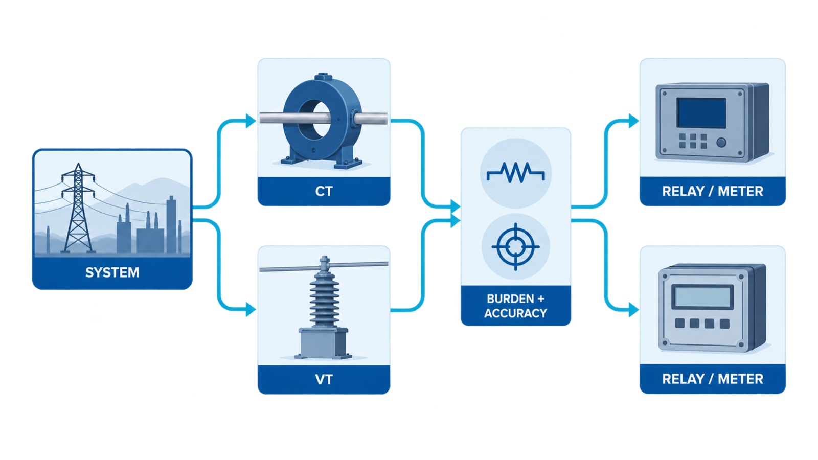
Define the function before the ratio
Metering and protection do not necessarily want the same behavior.
A metering CT is generally selected to maintain specified accuracy over its measurement range and to coordinate appropriately with connected metering equipment. A protection CT must reproduce fault current with sufficient fidelity for the intended protection function, considering saturation and transient conditions. A VT for revenue metering may prioritize a different accuracy range and burden from a VT feeding protection or synchronizing functions.
For every core or winding, record:
- connected device and input requirement;
- measurement, metering, or protection function;
- normal operating range;
- maximum credible fault or overvoltage condition;
- required accuracy or protection class;
- connected burden and lead length;
- redundancy and isolation requirements;
- test-switch and maintenance arrangement.
Separate cores or windings are often appropriate when functions have conflicting performance, security, or maintenance needs. Do not assume one shared secondary is acceptable merely because the total volt-amperes appear low.
CT selection: the decisive checks
Primary ratio and normal operating range
Choose a primary rating that covers expected continuous load and planned growth while preserving useful resolution at normal and low load. Excessive ratio margin can reduce measurement usefulness and may affect protection sensitivity. Too little margin can cause continuous overload or leave no credible operating headroom.
Use the actual load forecast and protection study, not transformer or cable nameplate current alone.
Secondary current and lead burden
The secondary rating must match the connected devices and project standard. Lead loss follows:
S_lead = I_secondary² × R_loop
where S_lead is lead burden in volt-amperes, I_secondary is secondary current, and R_loop is the complete secondary-loop resistance.
For the same loop resistance, a 1 A circuit produces one twenty-fifth of the lead VA of a 5 A circuit because burden varies with current squared. That does not make 1 A universally preferable: existing equipment, test practices, signal-to-noise behavior, standardization, and relay inputs must also match.
Total burden
Add the burden of relays or meters, connecting leads, test switches, transducers, and relevant terminals at the stated secondary current and frequency. Use the connected device’s specified input burden rather than a guess. Confirm both minimum and maximum conditions when the class or device requires them.
Protection performance and saturation
Protection CT selection must consider:
- maximum symmetrical and asymmetrical fault current;
- system X/R ratio and DC offset;
- relay operating principle and required waveform fidelity;
- remanence and transient performance where material;
- secondary-loop resistance and connected burden;
- CT excitation characteristics or class parameters required by the chosen standard;
- differential-zone through-fault performance and CT matching;
- short-time thermal and dynamic withstand.
A larger ratio, higher nominal accuracy class, or larger core does not automatically solve every saturation problem. The protection study must show that the CT and relay operate together for internal faults while remaining secure for external faults and expected transients.
Physical and insulation requirements
Check system highest voltage, insulation level, primary construction, window or bushing dimensions, conductor fit, creepage and environmental needs, polarity marking, terminals, mounting, temperature range, altitude, indoor or outdoor service, and seismic or mechanical requirements when applicable.
VT selection: the decisive checks
Primary and secondary voltage ratings
Match the primary rating and connection to the system nominal voltage, grounding arrangement, and whether the VT is connected phase-to-phase, phase-to-neutral, or in another engineered arrangement. Confirm the secondary voltage required by every connected device.
System grounding is central. The voltage imposed on a phase-to-ground VT during an earth fault depends on the network and connection. This affects the required voltage factor, thermal duration, insulation, and protection design.
Accuracy and burden
Calculate the total burden of meters, relays, recorders, leads, fuses, and auxiliary devices. Verify the required class over the actual burden and voltage range. Avoid treating a nameplate burden as a target; the connected circuit must fall within the conditions under which the required performance is specified.
Protection, resonance, and transient behavior
Evaluate:
- primary and secondary fuse or protective-device coordination;
- ferroresonance risk in the specific network and switching arrangement;
- residual-voltage or open-delta functions where required;
- transient response for the connected protection and recording functions;
- discharge, isolation, and test provisions;
- prevention of secondary backfeed during maintenance.
There is no universal anti-ferroresonance device or connection suitable for every system. The network capacitance, grounding, VT design, switching, and damping arrangement must be assessed together.
Selection matrix
| Decision area | CT question | VT question | Evidence required |
|---|---|---|---|
| Function | Metering, protection, differential, recording, control? | Metering, protection, synchronizing, residual voltage, control? | Protection philosophy, metering specification, one-line diagram |
| Primary rating | Normal current, growth, overload, fault current? | Nominal and highest system voltage, grounding, connection? | Load forecast, fault study, system data |
| Secondary interface | 1 A, 5 A, low-power, or digital interface? | Required secondary voltage, low-power, or digital interface? | Relay, meter, recorder, or merging-unit data |
| Accuracy | Range and class for each core? | Range and class for each winding? | Applicable IEC/IEEE project standard |
| Burden | Device burden plus complete lead loop? | Device burden plus leads and protective components? | Cable schedule, loop resistance, input burdens |
| Abnormal duty | Saturation, transient performance, thermal and dynamic withstand? | Voltage factor, fault duration, ferroresonance, transient response? | Fault study, grounding study, switching assessment |
| Installation | Window, conductor, polarity, insulation, environment? | Insulation, mounting, connection, environment? | Layout, insulation coordination, site conditions |
| Maintenance | Shorting and test facilities? | Isolation, fusing, anti-backfeed and test facilities? | Test philosophy and safe-work procedure |
Common selection mistakes
Choosing from load current alone
Load current does not establish fault performance, burden, accuracy, insulation, or protection requirements. Use the load forecast and fault study together.
Ignoring cable resistance
Long CT secondary runs can dominate the burden, particularly at higher secondary current. Calculate the complete loop, including return conductor and test hardware.
Sharing one core without checking interactions
Multiple connected devices change burden and maintenance risk. A disconnected meter, open test switch, or device replacement can affect the entire secondary circuit.
Treating metering and protection classes as upgrades of one another
They address different performance objectives. Select the class for the function rather than assuming a numerically “better” class solves both.
Omitting grounding and test arrangements
Secondary grounding point, shorting facilities for CTs, VT isolation, fusing, test blocks, and maintenance access should appear on drawings and schedules before construction.
Failing to verify relay input assumptions
Modern numerical relays may accept several nominal inputs or low-power signals, but settings, scaling, dynamic range, and test procedures must match the installed transformer and wiring.
Specification and review checklist
- Function and connected devices are identified for every core or winding.
- Applicable standard system and edition are stated.
- System voltage, grounding, frequency, insulation, and site conditions are documented.
- CT ratio is checked at normal load and maximum credible fault duty.
- VT ratio and connection match the network and protection functions.
- Complete secondary burden is calculated from device data and wiring.
- Accuracy and protection performance are verified at the stated burden.
- CT saturation, transient behavior, and short-time withstand are addressed where required.
- VT voltage factor, fault duration, resonance, and protection are addressed where required.
- Secondary grounding, fusing, shorting, isolation, and test blocks are shown.
- Polarity, terminal references, and relay/meter scaling are included in commissioning checks.
- Test reports and as-built settings are retained with the protection documentation.
Sources
- IEC 61869-1:2023 — General requirements for instrument transformers
- IEC 61869-2:2012 — Additional requirements for current transformers
- IEC 61869-3:2011 — Additional requirements for inductive voltage transformers
- IEC 61869-20:2025 — Safety requirements for instrument transformers for high-voltage applications
- IEEE C57.13-2016 — Standard Requirements for Instrument Transformers