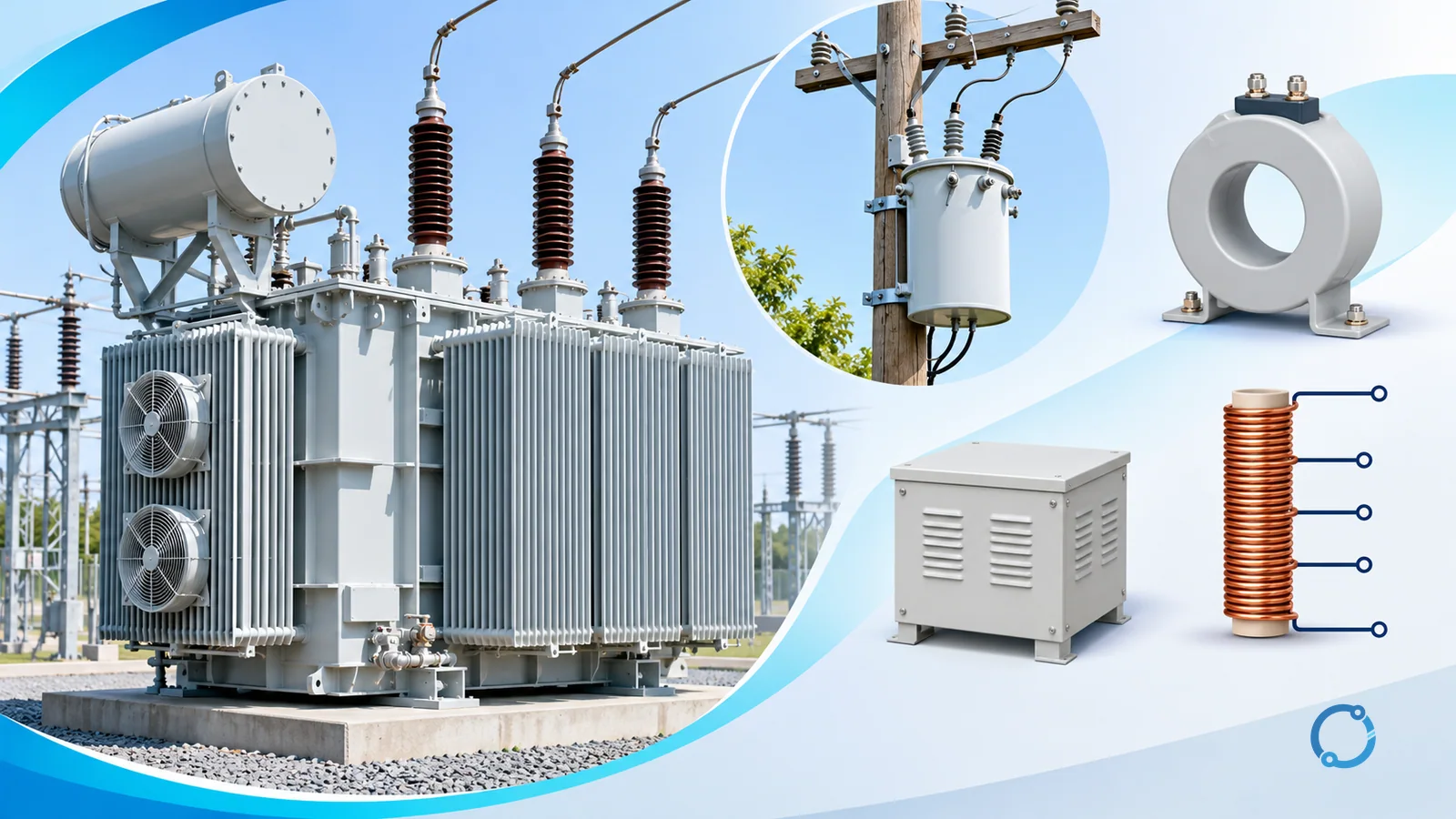
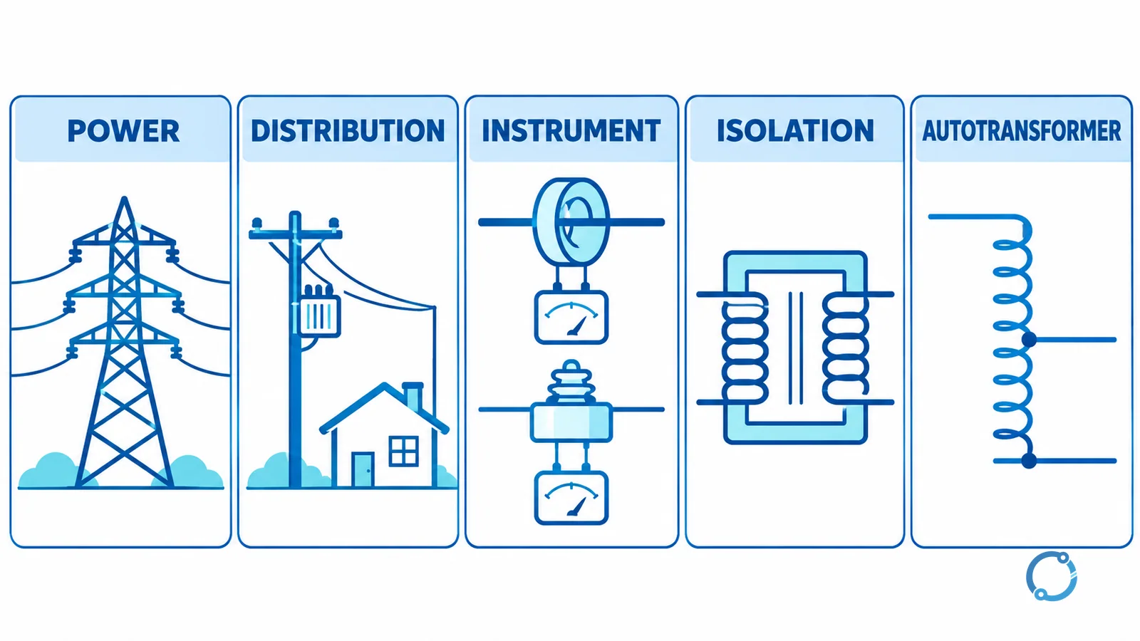
Short answer: Transformers can be grouped into five practical families by purpose and winding arrangement: power transformers transfer energy at major generation or transmission interfaces, distribution transformers serve the final stages of voltage delivery, instrument transformers reproduce current or voltage for measurement and protection, isolation transformers separate circuits magnetically, and autotransformers change voltage through a shared winding without galvanic isolation.
| Transformer family | Voltage relationship | Main purpose | Typical qualitative location |
|---|---|---|---|
| Power transformer | Step-up, step-down or system interconnection | Bulk power transfer | Generating stations and transmission substations |
| Distribution transformer | Usually final step-down toward utilization voltage | Supply local distribution loads | Distribution substations, networks and service areas |
| Instrument transformer | Proportional current or voltage reproduction | Measurement, metering and protection input | Switchgear and substations |
| Isolation transformer | Often 1:1, with separate windings | Galvanic separation and controlled reference | Control, test and sensitive equipment circuits |
| Autotransformer | Step-up, step-down or adjustable ratio through one tapped winding | Efficient voltage conversion where isolation is not required | Network interconnection, starting or controlled-voltage duties |
These labels describe system jobs, not one universal physical size. A dry indoor unit, a liquid-immersed outdoor unit and a compact panel transformer can all use electromagnetic induction while serving very different purposes. This article maps the types; it does not size, specify or install them.
The common transformer principle
A transformer transfers AC energy through changing magnetic flux linking windings on a magnetic core. The applied primary voltage establishes alternating flux; that flux induces voltage in another winding. The turns ratio relates the ideal winding voltages, while real current, loss, impedance, insulation and cooling determine practical behavior.
The full mechanism and electromotive-force equation are covered in how a transformer works. For this overview, the important point is that transformer type comes from what the device must do and whether its windings are electrically separate.
Power transformers
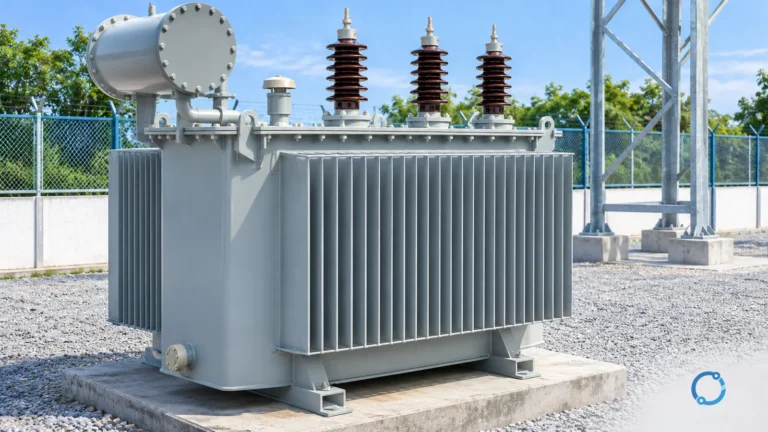
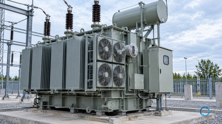
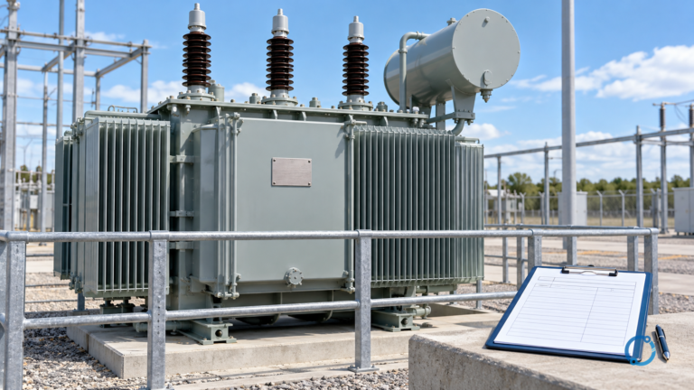
A power transformer transfers substantial electrical power between parts of a generation, transmission or substation system. It may raise generator voltage for transmission, lower transmission voltage at a substation or connect systems with different voltage arrangements.
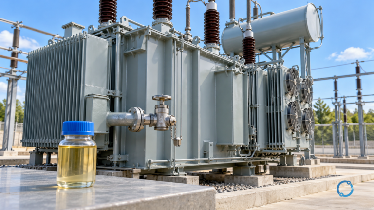
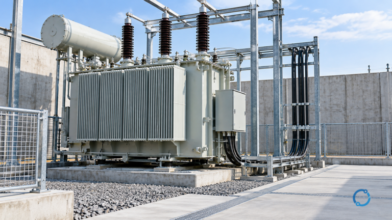
The defining idea is the bulk-power system role rather than one fixed rating. Power transformers are engineered around system voltage, power duty, insulation coordination, cooling, losses, impedance, short-circuit forces, tap arrangement and transport constraints. Liquid-immersed construction is common in many utility applications, while special dry-type or other designs also exist within defined scopes.
Power transformer and distribution transformer are not perfectly separated by one universal numerical boundary. Industry standards, utilities and regulations may classify equipment by voltage, power and application. In this article, “power transformer” means the upstream bulk-transfer role, while “distribution transformer” means the final delivery role nearer end users.
The name alone cannot determine capacity. The transformer kVA selection guide owns the load-and-duty calculation, while transformer kVA rating basis explains why apparent power is the relevant rating language.
Distribution transformers
A distribution transformer performs the final transformer stage or stages that deliver power into a local distribution system or utilization network. It commonly reduces voltage nearer to buildings, facilities or groups of loads.
Its design priorities reflect that location. Distribution load varies over time, so no-load loss, load loss, temperature rise and expected duty can all matter. The unit may be pole-mounted, pad-mounted, vault-installed or integrated into an indoor distribution arrangement, depending on the network.
Distribution transformers can be liquid-immersed or dry-type. That distinction describes insulation and cooling construction, not the transformer’s basic electromagnetic purpose. A dry-type unit does not automatically belong indoors in every case, and a liquid-immersed unit does not define one voltage class. Enclosure, environmental class, fire behavior and installation rules must match the actual location.
The practical difference from a power transformer is therefore primarily system role: the power transformer moves bulk power between major network levels; the distribution transformer delivers power through the final local voltage transformation. The exact classification should follow the applicable standard, utility practice and project specification.
Instrument transformers
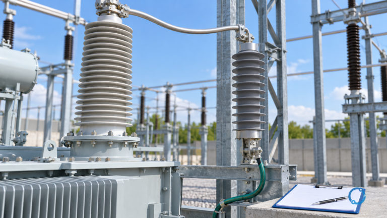
Instrument transformers reproduce a high system current or voltage as a smaller, defined quantity suitable for meters, relays and control equipment. They also establish an insulation boundary between the primary power system and secondary measurement circuits, subject to the design and standard.
Current transformers
A current transformer (CT) is connected so the primary current produces a proportional secondary current. In some constructions, the primary is a conductor or bus passing through the magnetic core; in others, the CT has a wound primary. The secondary feeds metering or protective equipment.
A CT is not a small power transformer for supplying arbitrary loads. Ratio, accuracy class, burden, saturation behavior, insulation and protection duty all affect application. An open secondary on an energized CT can be hazardous; installation and testing require qualified procedures. The current transformer selection criteria page covers that separate engineering task.
Voltage transformers
A voltage transformer (VT), also called a potential transformer in some contexts, produces a proportional secondary voltage for measurement or protection. It connects across the system rather than carrying the line current in series like a CT.
Ratio, burden, accuracy, insulation and ferroresonance or grounding considerations depend on the system and construction. The dedicated voltage transformer selection guide for substations addresses those inputs. CT and VT are grouped together as instrument transformers because both interface the power system with instruments and relays, not because their primary connections are interchangeable.
Isolation transformers
An isolation transformer uses separate primary and secondary windings so there is no intentional conductive path between the two circuits. Energy crosses through magnetic coupling. A 1:1 turns ratio is common when the goal is separation rather than a nominal voltage change, but isolation transformers can also have different primary and secondary voltages.
Electrical separation can support controlled grounding, noise-management or safety architectures when the complete system is designed for that purpose. The word “isolation” does not mean that all high-frequency noise disappears, that touch protection is automatic or that secondary grounding can be ignored. Capacitance, shielding, bonding, insulation and downstream circuit arrangement affect the real result.
A control transformer can use separate windings and may provide isolation while changing voltage for control loads. Sizing it for contactor-coil inrush and sealed demand is a separate calculation; see control transformer sizing for contactor coils.
Autotransformers
An autotransformer uses one continuous winding with one or more taps. Part of the winding is common to both input and output, so energy transfer occurs through a combination of magnetic induction and direct conductive connection.
Sharing winding material can make an autotransformer compact and efficient for suitable voltage ratios. It can serve step-up, step-down, interconnection, motor-starting or adjustable-voltage functions, depending on design. However, the shared winding means there is no galvanic isolation between primary and secondary.
That one fact is the decisive boundary. An autotransformer must not replace an isolation transformer where electrical separation is a required function. The conductor relationships, earthing, protection and fault transfer must be evaluated for the actual system.
IEC 60076-1 includes autotransformers within its broad power-transformer scope, but a standard’s scope does not establish that a particular product is suitable or compliant. The IEC 60076 transformer specification guide explains how project requirements are translated into a verifiable specification.
Turns ratio in plain terms
For an ideal transformer, winding turns and voltage follow:
N1 / N2 = V1 / V2
where N1 and N2 are primary and secondary turns, and V1 and V2 are the corresponding winding voltages.
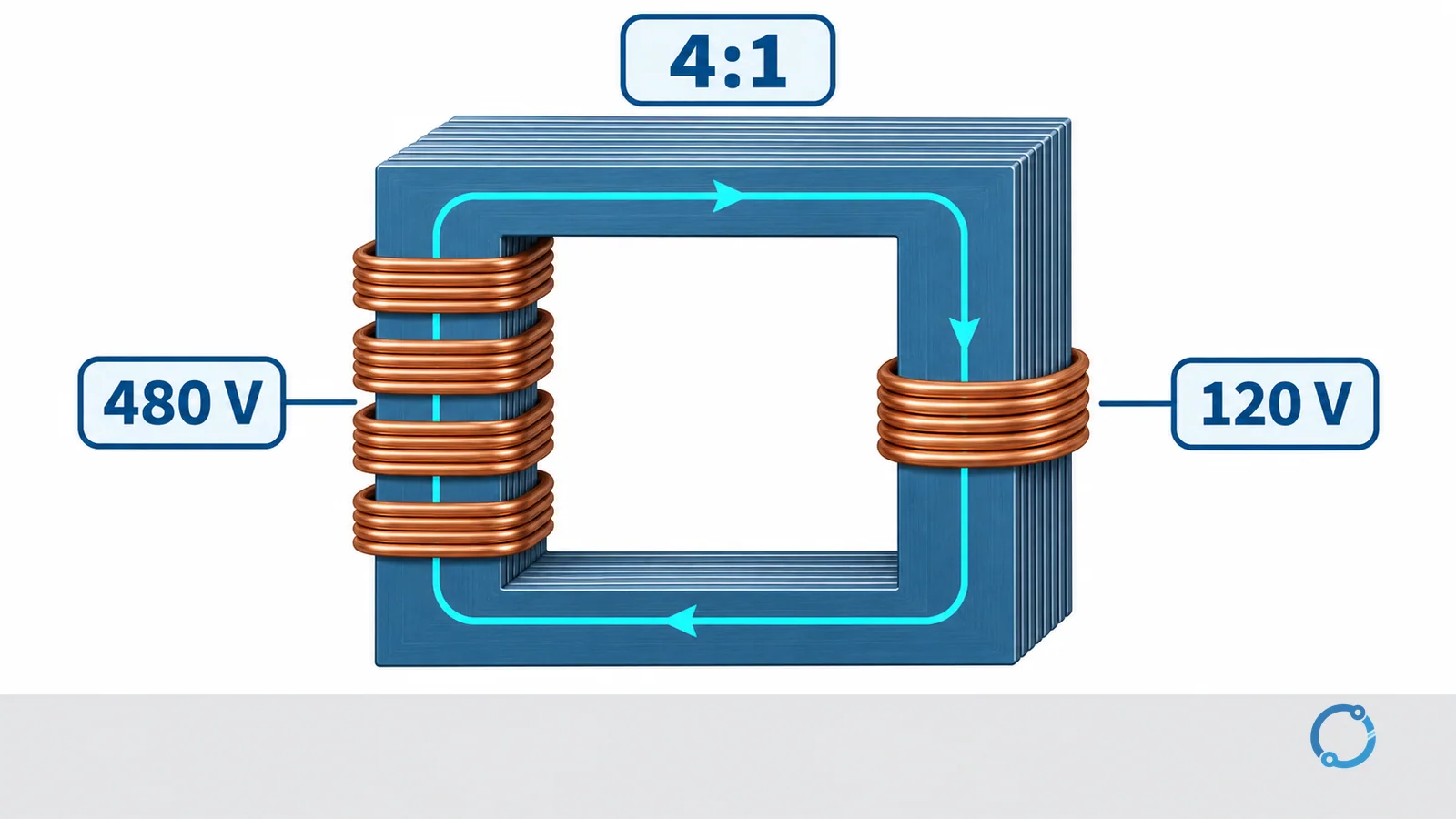
Consider the required hypothetical control-transformer example:
- primary voltage:
480 V; - secondary voltage:
120 V.
The voltage and ideal turns ratio is:
N1 / N2 = V1 / V2 = 480 / 120 = 4:1
The primary therefore has four times as many turns as the secondary in this simplified ratio model. If the primary had 400 turns, the ideal secondary relationship would use 100 turns. The example explains ratio only; it does not establish conductor size, kVA, regulation, inrush, insulation or a control-transformer selection.
Three easy-to-confuse pairs
Isolation transformer versus autotransformer
An isolation transformer has separate windings and no intentional conductive primary-to-secondary path. An autotransformer shares part of one winding and therefore does not provide galvanic isolation.
Power transformer versus distribution transformer
A power transformer occupies a bulk-transfer role between major system levels. A distribution transformer serves the final local delivery stages. Exact classification can depend on the governing standard and utility context rather than one worldwide rating cutoff.
CT versus VT
A CT reproduces line current for measurement or protection and is connected in the current path. A VT reproduces system voltage and is connected across the voltage being measured. Their secondary safety rules and application checks differ.
How to identify the type from a specification
Start with function before appearance:
- Ask whether the unit transfers usable power or supplies a measurement/protection signal.
- Identify whether the system location is bulk transmission, final distribution, control equipment or instrumentation.
- Determine whether primary and secondary windings are separate or share a winding section.
- Check whether the output is intended to supply a load, a meter, a relay or a control circuit.
- Verify the applicable standard, insulation level, cooling construction and system earthing.
This sequence prevents a common category error: calling every voltage-changing device a distribution transformer, or assuming every small transformer is an instrument transformer. Physical size alone cannot establish function.
Nameplate and drawing language should confirm the classification. A power or distribution transformer specification emphasizes rated power, winding voltages, impedance, cooling and insulation system. An instrument-transformer specification emphasizes ratio, burden, accuracy and protection performance. An isolation-transformer specification must establish separate windings and the intended system reference, while an autotransformer drawing reveals the shared winding connection.
The surrounding circuit provides another clue. A CT primary is in the current path and its secondary feeds metering or protection. A VT primary is connected across the system voltage. A distribution transformer supplies a downstream network, and an autotransformer directly connects part of its winding to both sides. These relationships are more reliable identifiers than enclosure shape or physical size.
When a document uses a broad label such as “power transformer,” read the declared scope before assuming the category. Project terminology can be broader or narrower than an educational overview, and the governing specification controls the actual equipment requirements.
Common classification mistakes
Assuming a 1:1 ratio always means isolation
A 1:1 voltage ratio does not by itself prove separate windings or a verified isolation function. The construction and documentation must establish the separation.
Treating CTs and VTs as ordinary load transformers
Instrument transformers are designed to feed defined metering or protection burdens. Their accuracy, saturation and secondary safety requirements differ from transformers intended to supply general loads.
Treating oil-filled and dry-type as separate purposes
Liquid-immersed and dry-type describe construction and cooling/insulation approaches. Either term must still be paired with the transformer’s actual system role and applicable standard.
FAQ
What are the five main types of transformers in this guide?
The five practical families are power, distribution, instrument, isolation and autotransformers. They are grouped by system purpose and by whether the windings are separate or shared.
What is the difference between a power transformer and a distribution transformer?
A power transformer serves bulk transfer between major generation, transmission or substation levels. A distribution transformer serves the final local stages that deliver voltage nearer to loads. Exact classification depends on the governing standard and system context.
What is the difference between a CT and a VT?
A current transformer reproduces system current for meters or relays and is connected in the current path. A voltage transformer reproduces system voltage and is connected across the measured voltage. Their ratios, burdens and secondary safety rules are different.
Does an autotransformer provide electrical isolation?
No. An autotransformer has a shared winding section, creating an intentional conductive relationship between input and output. Use a transformer with separate windings when galvanic isolation is required.
What does a 4:1 transformer turns ratio mean?
It means the primary has four times the turns of the secondary in the ideal ratio model, and the primary voltage is four times the secondary voltage. In the stated example, 480/120 = 4:1.