

An optical arc-flash relay detects a specified event and initiates a mitigation command. It does not, by itself, interrupt fault current or establish installation-code compliance. Before crediting the scheme, verify sensor coverage, decision logic, every required clearing device and the evidence for the complete response.
This guide concerns optical internal-arc detection in industrial low-voltage (LV) switchgear. It is not a household arc-fault circuit interrupter (AFCI) guide, an incident-energy calculation or permission for energized work. Medium-voltage applications need their own device, equipment and integration evidence.
Separate detection, clearing and compliance
IEC 60947-9-2:2021 covers internal arc-fault control devices that process at least the optical effect of an internal arc and operate a mitigation device. That is a device-function scope, not a certificate for a particular relay or complete switchboard.
Three questions need separate answers:
| Question | Evidence boundary | What does not answer it |
|---|---|---|
| Does the selected device perform its declared function? | Identified device, sensor arrangement, conditions and applicable evaluation evidence | A generic standards reference |
| Does the installed scheme deliver the intended mitigation? | Sensor zones, logic, supplies, interfaces, clearing devices and assembly integration | A successful sensor indication alone |
| Does the installation/task satisfy applicable requirements? | Adopted code, engineering assessment, documentation and workplace-safety program | The presence of a device called an arc-flash relay |
The broader arc-flash risk-reduction framework separates prevention, exposure reduction and consequence control. Here the focus is the evidence for one optical detection-and-clearing scheme.
1. Define the zones that the sensors actually cover
Start from the assembly compartments and the locations of credible internal faults. Map each sensor or sensing-fiber region to its intended zone and to the clearing action for that zone.
Point sensors and distributed optical sensing arrangements have different physical coverage. For either, ask whether partitions, installed equipment, cable routing or the actual sensing arrangement affect detection. Do not infer complete coverage from a sensor count or a line drawn through the cabinet.
Record which regions are outside the scheme. For a fault on the supply side of a main breaker, opening that breaker may not remove the supply contribution. Sensor reach and clearing reach are independent boundaries. If an upstream trip is needed, its interface, operating authority and response must be part of the engineered scheme.
Use the actual assembly arrangement and the device’s accepted installation conditions. “One sensor per compartment” is not a universal design rule, and adding a sensor without revisiting the action map can create an unintended trip destination.
2. Understand any current-supervision logic
Optical detection may be used alone or with an additional condition, such as a current criterion. Current supervision can prevent an optical stimulus alone from producing the selected trip, but it introduces another input whose source, reach and behavior must be verified.
For clarity, consider an illustrative healthy-channel AND scheme. A trip decision requires both the defined optical condition and the defined current condition:
| Optical condition met? | Current condition met? | Decision in this hypothetical scheme |
|---|---|---|
| No | No | No optical-scheme trip |
| Yes | No | No optical-scheme trip |
| No | Yes | No optical-scheme trip; other protection may act |
| Yes | Yes | Issue the mapped mitigation/trip command |
This truth table is not the operating logic of every relay. It assumes valid inputs and does not prescribe thresholds or failure responses. Some schemes use different combinations, timing or zone logic.
For the actual design, identify the current source and confirm that the studied fault produces the required current condition at that source in all relevant operating modes. Include the case where current is below the supervising criterion. Decide how a failed sensor, unavailable current input, lost supply or disabled function is indicated and handled; “fail safe” without a defined response is not a completed design.
3. Trace the command to removal of all fault contributions
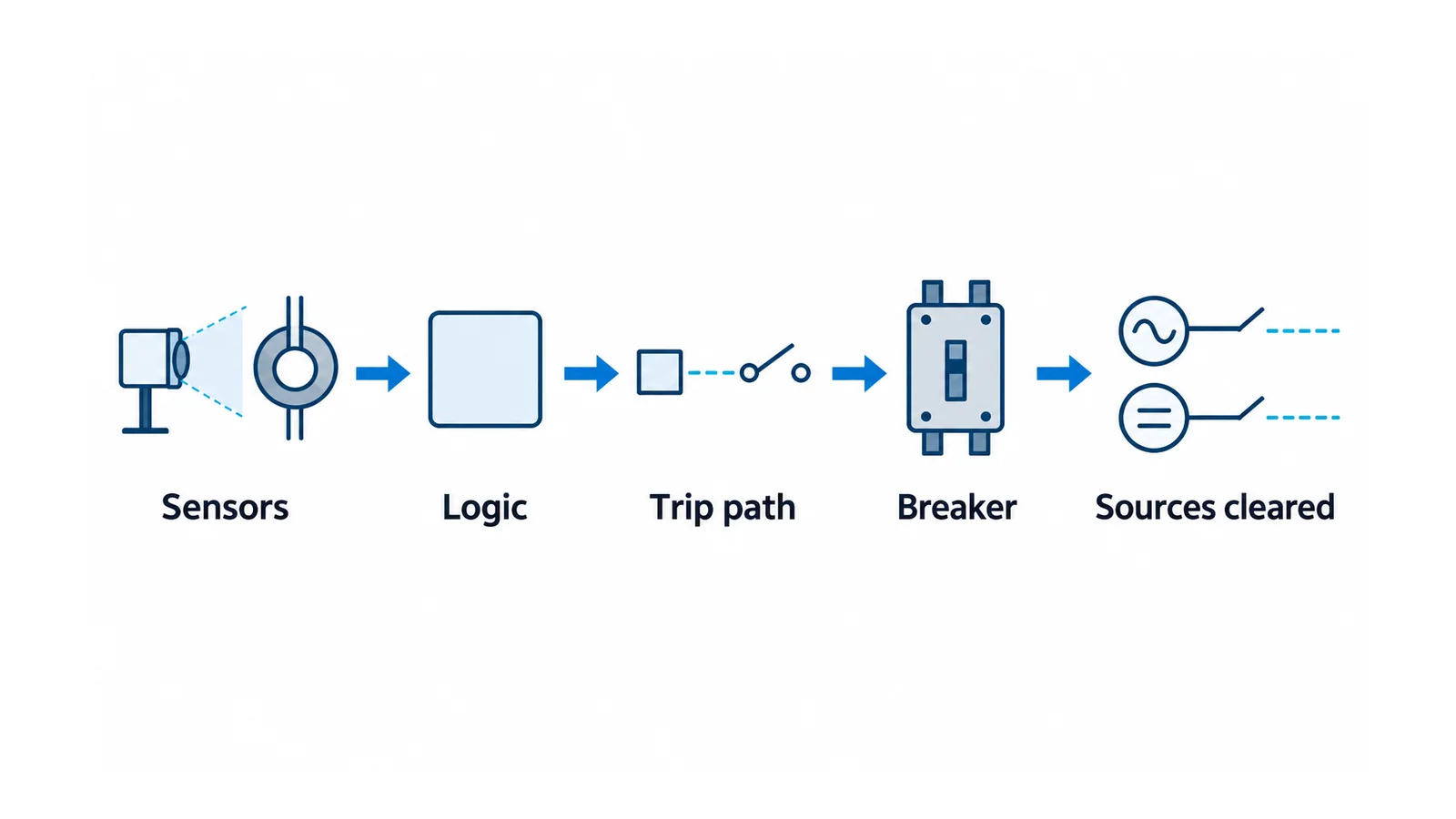
Follow sensor input → decision/output → trip interface and supply → interrupting device → removal of the relevant source contributions. Include an interposing relay, communications or upstream interface if the actual arrangement uses them.
For multiple sources, determine which devices must act and whether a remaining source can continue feeding the fault. Do not stop the trace at the first breaker that receives a command. The physical DC/output path can be reviewed using the trip-circuit design checklist, with the installation-specific differences retained.
A timing example with explicit endpoints
Suppose a hypothetical sequential chain has these non-overlapping intervals:
- event initiation to valid sensor indication: 2 ms;
- valid indication to issued relay output: 1 ms;
- issued output to breaker trip-coil energization: 3 ms;
- trip-coil energization to interruption of the modeled contribution: 50 ms.
The illustrated total is 2 + 1 + 3 + 50 = 56 ms = 0.056 s. The values are invented to explain accounting, not product specifications, measured results or recommended acceptance limits. A 1-ms relay-output interval would not make this a 1-ms clearing scheme.
Real quoted times may already include some of these intervals; do not double-count them. Parallel paths, current-supervision availability and several clearing devices need an event timeline rather than a blind sum. Define which endpoint establishes final removal of the contribution in the study.
Any claimed incident-energy benefit needs the applicable system model and operating cases. Do not turn the time example into a reduction percentage or scale an existing label by 56 ms. The separate clearing-time and incident-energy explainer explains that analytical boundary.
4. Build a controlled acceptance matrix
The following is a planning matrix, not an instruction to stimulate a live fault. Tests belong to authorized, qualified personnel under an approved segregated test setup or outage plan, with unintended trip paths controlled.
| Function to verify | Evidence to record | Unresolved condition that prevents crediting the function |
|---|---|---|
| Detection coverage | Sensor identity, zone and installed arrangement | Intended region has no demonstrated coverage |
| Supervised logic, where used | Expected responses for the agreed input combinations and timing | Current condition or receiving logic is assumed |
| Trip destination | Correct output/consumer and absence of unintended destinations | A neighboring zone or wrong breaker can be operated |
| End-to-end response | Defined endpoints, actual chain and suitable timing evidence | Only sensor or packet time is available |
| Impairment handling | Approved behavior for lost sensor/input, supply or disabled function | Credited protection can disappear without the intended indication/control |
| Restoration and baseline | Settings, mappings, enabled state and as-built revision reconciled | Test isolation or a disabled function remains after restoration |
A functional test exercises only its defined scope. Device conformance, scheme logic tests, breaker timing evidence and assembly internal-arc performance are not interchangeable. Never create an actual arc as an informal commissioning demonstration.
5. Keep a scoped compliance dossier
IEC TS 61641:2026, published on 19 August 2026, addresses internal arc-fault protection of LV assemblies, including passive construction and integrated active systems. It replaces IEC TR 61641:2014 and IEC TS 63107:2020. Its public scope expressly excludes maintenance-work conditions and personal protective equipment (PPE), and does not cover integration of household AFDDs under IEC 62606.
For an IEC assembly claim, obtain the applicable device and assembly evidence for the actual integration. For a US installation-code claim, identify the locally adopted NEC edition, the exact applicable arc-energy-reduction provision and the documentation/performance criteria that the responsible authority requires. This article does not reproduce an inaccessible code clause or assert that every optical relay meets it.
Workplace safety remains another boundary. OSHA 1910.333 requires de-energization of exposed live parts in US general-industry work unless its specified exceptions apply. Installing mitigation does not create an exception. OSHA’s arc-flash guidance supports hazard assessment and controls; it is guidance, not a new regulation.
Retain the zone/action map, logic and source assumptions, timing evidence, device/assembly records, adopted-requirement review, test results and restoration record. Reassess after changes to partitions, sensors, supplies, breakers, logic or network paths. Credit only the demonstrated function; refer unresolved clearing or safety assumptions to the responsible engineer and operating authority.
Sources
- IEC 60947-9-2:2021: optical internal-arc detection/mitigation device scope.
- IEC TS 61641:2026: LV assembly integration and scope exclusions.
- OSHA 1910.333: US general-industry electrical work practices.
- OSHA — Protecting Employees from Electric-Arc Flash Hazards, November 2024: workplace hazard-assessment guidance.