
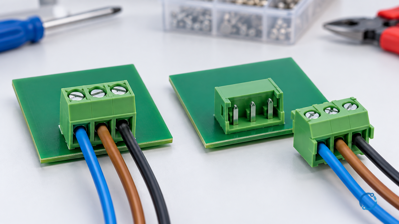
Choose a fixed PCB terminal block when the wiring can remain with the board or be individually released during service. Consider a matched pluggable interface when the harness must disconnect from the board as an assembly. Then choose the conductor-clamping method separately: a pluggable connector can itself use screws. “Screw versus pluggable” is therefore not a clean either/or comparison.
The 5.08 mm figure describes nominal centre-to-centre contact pitch. It is not a voltage rating, current rating, wire range, touch-protection declaration or guarantee that two connectors mate. This guide produces a shortlist for a PCB interface; it does not approve a board’s insulation coordination or substitute for an equipment safety assessment.
Separate the two design axes
| Axis | Options | What it changes |
|---|---|---|
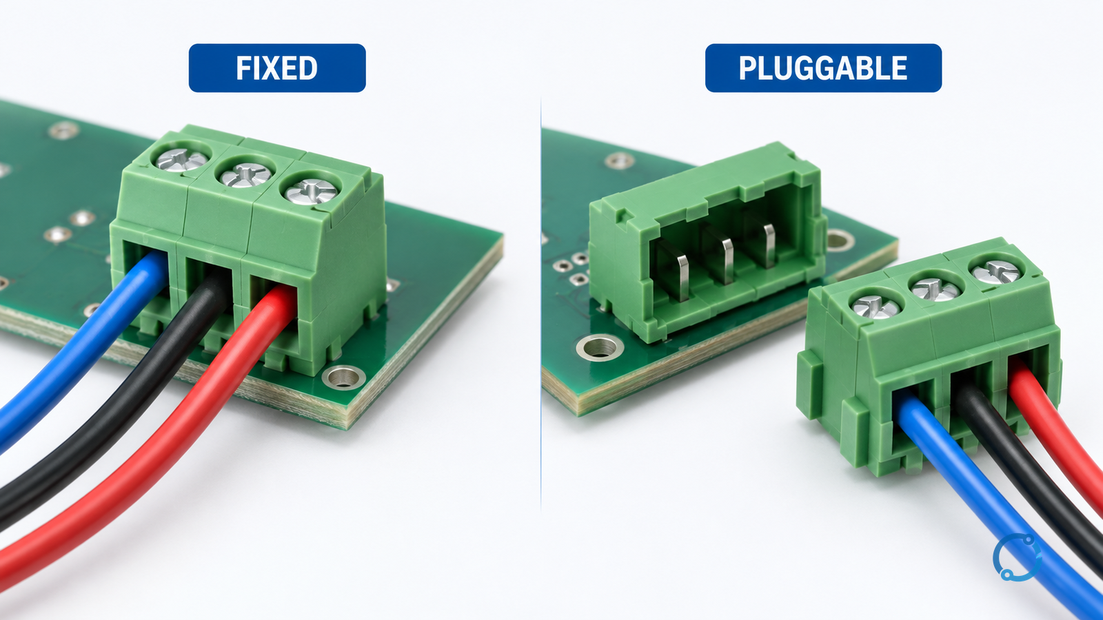
| Connection to the board | Fixed terminal assembly or separable plug/header pair | Whether the harness can disconnect as a unit |
| Conductor retention | Screw-operated or suitable screwless clamping arrangement | Wire preparation, connection procedure and accessible service task |
The first axis describes the separable interface. The second describes how a wire is held. Compare real combinations, such as a fixed screw-clamp block and a pluggable screw-clamp pair, before introducing another variable.
IEC 60947-7-4:2019 addresses PCB terminal blocks for industrial and similar applications. IEC 60999-1:1999 addresses screw-type and screwless clamping units for copper conductors. These public scopes help distinguish the questions; they do not establish that an unspecified product meets either standard.
Use service access as the first architecture test
Ask what actually needs to move during replacement. With a fixed block, releasing individual conductors may be acceptable if access, wire identification and verification are well controlled. With a pluggable pair, the harness can remain terminated while the board is removed—but the design adds mating contacts, retention and another possible misconnection.
Neither architecture is automatically more reliable. Infrequent board replacement, available access and a stable harness can favour a fixed arrangement. Repeated module removal or constrained termination access can make a pluggable arrangement useful, provided matching, retention and service-cycle requirements are verified.
Keep this PCB task distinct from DIN-rail terminal selection in panels. A board-mounted header introduces footprint, solder or other mounting, board loading and assembly-clearance questions that a rail-block shortlist does not answer.
Exclude unsuitable candidates before comparing convenience
| Requirement | Evidence to obtain | Reject or redesign when |
|---|---|---|
| Electrical application | Declared ratings and conditions for the exact parts | Pitch is the only evidence offered |
| Mating pair | Matched header/plug identifiers, orientation and keying | Similar pitch is being treated as interchangeability |
| PCB interface | Verified footprint, mounting method and mechanical support | Removal or cable loading exceeds the reviewed assembly design |
| Wire interface | Conductor type/range, preparation and terminal instructions | Intended wires or preparation are outside the declaration |
| Access | Tool clearance, insertion/removal path and cable bend space | Cabinet geometry blocks proper connection or inspection |
| Service safeguards | Identification, retention, isolation and exposed-contact review | A plausible wrong plug position or unsafe access remains uncontrolled |
Do not turn this matrix into a generic catalogue rating table. Ratings can depend on construction, conductor use, temperature and the applicable test framework. Record conditions along with numbers rather than comparing bare headline values.
Pitch is not creepage, clearance or board footprint
Nominal pitch locates adjacent contact centres. Clearance concerns an air path; creepage concerns a surface path. Housing shape, barriers, contact positions, board routing and the complete assembly affect those paths. A pitch dimension alone cannot determine them.
IEC 60664-1:2020+AMD1:2025 covers insulation coordination for equipment within its stated scope. Obtain the project-applicable edition and the actual assembly inputs before applying its requirements. This article provides no universal permissible voltage for a 5.08 mm interface.
Review the connector drawing and PCB layout together. Confirm holes or pads, mounting tolerances, insertion direction, neighbouring components and service envelope. “Fits the board” and “fits the harness” are separate checks. For the environmental input to an insulation review, see terminal-block pollution degree.
Review the conductors without assuming a ferrule solves everything
Select the conductor type and preparation permitted by the exact terminal. Solid, stranded and ferruled conductors can present different requirements; a ferrule is not automatically necessary or accepted for every connection. Use the solid-versus-stranded conductor guide for that separate choice, then return to the candidate’s instructions.
Do not specify a common strip length or torque from pitch. For a pluggable pair, also distinguish the wire-clamping instruction from the mating/retaining instruction. They are not the same operation.
Release the whole interface
The selection record should identify the fixed part or both halves of the pair, approved conductors, footprint revision, electrical conditions, support/retention features and service procedure. Review the actual assembled board, not only a loose connector sample.
Qualified personnel must isolate and verify the equipment before service. Unless the exact application explicitly permits a different operating task, do not treat separability as permission for energised unplugging. A successful choice is an interface that meets electrical and mechanical requirements and can be serviced as intended—not simply one with the preferred pitch.