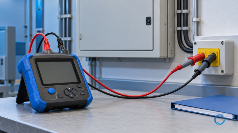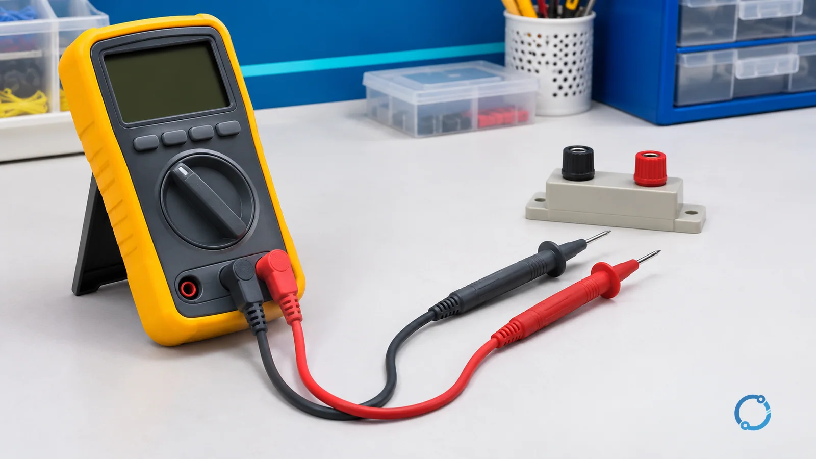
The first decision when using a multimeter is not which button to press. It is whether the meter, leads, probes, and selected function are rated for the circuit you are about to test. A multimeter can measure voltage, resistance, continuity, and current, but those modes do not share the same connection method or the same safety boundary.
Start with the meter’s measurement category and voltage rating. The IEC 61010-2-033 standard covers safety requirements for hand-held multimeters capable of measuring mains voltage and other quantities. The current IEC catalogue page describes that scope. A CAT rating is not simply a maximum number printed on the case; it represents the transient-overvoltage environment in which the meter and its leads are intended to be used. The voltage rating and category must both match the task, and the leads must have an appropriate rating as well.
If the meter’s category, the lead rating, or the condition of either item is unknown, stop. Use a properly rated instrument or ask a qualified person to establish the test method.
Pre-use safety gate
Before touching the probes to a circuit, inspect the complete measurement chain:
- Meter: confirm the model, category marking, voltage rating, and current-jack arrangement.
- Leads: check for cracked insulation, exposed conductor, loose strain relief, damaged probe tips, and missing finger guards.
- Jacks and fuses: verify that the leads are in the correct sockets for the selected function. A current jack can create a dangerous path if the meter is later connected across a voltage source.
- Battery and display: replace a weak battery or stop if the display is unstable, dim, or showing a low-battery warning.
- Test points: identify the points to be measured and determine whether they are exposed, guarded, isolated, or still connected to stored energy.
- Environment: confirm the working area, gloves, barriers, and local procedure. A meter does not turn an unqualified person into a qualified electrical worker.
The eCFR text of 29 CFR 1910.333 provides the regulatory context for de-energizing, isolating, and verifying equipment. The exact site procedure and the employer’s electrical-safety program remain controlling.
The live-dead-live check
Use a live-dead-live sequence whenever the task requires proving that a circuit is de-energized:
- Live check: verify the meter on a known energized source of the appropriate type and range.
- Target check: test the target circuit at every relevant terminal or phase.
- Live check again: return to the known source and confirm the meter still responds correctly.
The final check is important because a meter, lead, fuse, or connection can fail between the first and second readings. A zero-volt display is not proof of a dead circuit if the instrument was not proved before and after the test.
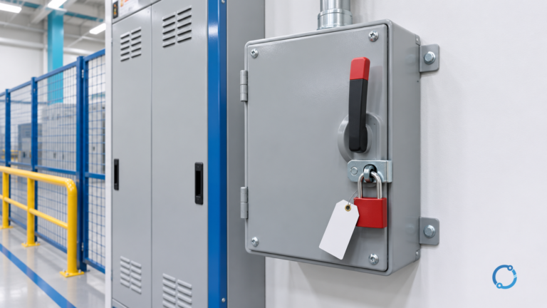
The lockout/tagout guide for electrical work explains why isolation, lockout, and verification belong to one controlled process. The temporary jobsite power verification workflow applies the same principle to a temporary distribution setup.
Measure voltage in parallel
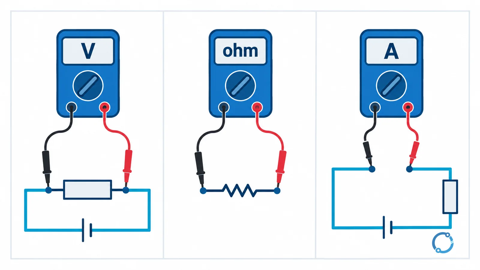
Voltage is a difference between two points. A voltmeter is connected across those points, in parallel with the component or source being measured. The U.S. Department of Energy test-instrument handbook states that voltmeters are connected in parallel with the load.
Voltage procedure
- Select AC or DC voltage as appropriate for the expected supply.
- Select a range above the expected value, or use auto-ranging if the meter provides it.
- Confirm the leads are in the voltage and common jacks, not the current jack.
- Connect the common lead to the reference point and the other lead to the point being compared.
- Read the display without changing the probe position or touching exposed conductors.
- If the reading is unexpected, stop and reassess the circuit rather than switching modes at the live test point.
For a DC measurement, the sign indicates the polarity of the probe connection relative to the reference. For an AC measurement, the displayed value may be an RMS quantity; verify the meter’s specification if waveform shape or frequency matters.
Do not assume that a voltage reading across an open switch, a blown fuse, or a control relay proves the entire circuit is de-energized. Voltage can be present on one side of an open device, and a meter can read a misleading value through an unintended path.
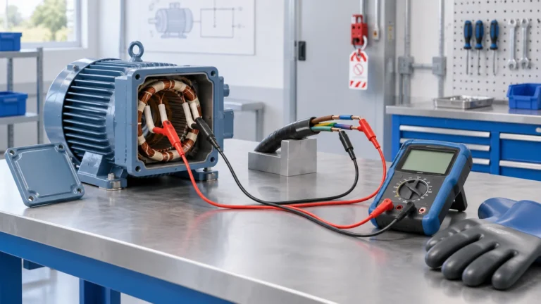
Measure resistance only after isolation
Resistance mode uses the meter’s own low-energy test signal. It is intended for a de-energized component or circuit. Before measuring resistance:
- Isolate the circuit from every source.
- Lock out and tag according to the site procedure.
- Verify the circuit is dead with a proved meter.
- Discharge stored energy in capacitors, drives, power supplies, or other energy-storage components using the approved method.
- Disconnect the component or remove parallel paths that would distort the reading.
- Select resistance mode and confirm the leads are in the correct jacks.
Do not use resistance mode on a circuit that may still be energized, even if the supply breaker is open. Backfeeds, stored energy, parallel sources, and control voltages can remain present.
Interpreting a resistance reading
An ohmmeter does not necessarily measure the component at its operating temperature or operating voltage. A reading is useful for comparison with an expected value, a previous record, or a manufacturer’s test instruction. It is not automatically a pass/fail result. The meter’s test current, range, lead resistance, and contact quality can all affect the number.
For insulation systems, a general-purpose multimeter is not a substitute for an insulation-resistance tester. The insulation-resistance testing procedure explains the different instrument, voltage, and interpretation requirements.
Continuity is a path check, not a safety proof
Continuity mode usually gives an audible or visual indication when the resistance between the probes is below a selected threshold. It is useful for checking a fuse, a switch contact, a terminal-to-terminal path, or a wire run after the circuit has been isolated.
Keep the limits in view:
- a beep does not prove that the conductor can carry load current;
- a beep does not prove that the insulation is sound;
- a beep can occur through a parallel path;
- a high-resistance connection may still beep on a low-sensitivity setting;
- a continuity reading on an energized circuit is invalid and unsafe.
When the actual resistance matters, use resistance mode and record the value and range. When the question is insulation quality, use the correct insulation test instrument.
Measure current in series
Current is the rate of charge movement through a path. To measure it, the meter must become part of that path. The DOE handbook states that an ammeter is placed in series with the circuit. That means the circuit is opened at a suitable point and the meter is inserted so the current passes through it.
Current procedure
- De-energize and isolate the circuit before changing the lead jacks or opening the circuit.
- Confirm the meter’s current range, fuse, and jack can accept the expected current.
- Select AC or DC current.
- Open the circuit at a point rated and approved for the test.
- Connect the meter in series with the load path.
- Re-energize only under the site’s authorized procedure.
- Read the current and then de-energize before removing the meter.
Never place the meter in parallel across a voltage source while it is in current mode. In current mode, the meter has a low-resistance shunt intended to carry current. Connecting that path across a supply can create a short circuit, cause a high current through the meter and leads, blow a fuse, produce an arc, or damage the instrument. The correct current connection is a deliberate series break, not a probe across two live terminals.
If the expected current is beyond the meter’s rated range, use a suitable clamp meter or another approved method. Do not rely on a meter’s highest displayed range as proof that its fuse, leads, and category rating are adequate.
Stop conditions
Stop the measurement and move to a safe state if any of the following occurs:
- a lead or probe is damaged, loose, or too hot to touch;
- the meter’s category or voltage rating cannot be established;
- the correct jack or range is unclear;
- the circuit cannot be isolated for a resistance or continuity test;
- stored energy cannot be discharged and verified;
- a current measurement requires opening a circuit outside the approved procedure;
- the display is erratic or the meter behaves differently from the live check;
- the test point is exposed and the required guarding or PPE is not in place.
For a power-quality investigation, a general multimeter may not capture the relevant events. The power-quality measurement and monitoring plan describes instrument selection, synchronization, and data-integrity checks for that different task.
A compact mode table
| Measurement | Meter connection | Circuit state | Main risk to control |
|---|---|---|---|
| Voltage | Across the two points, in parallel | As required by the authorized procedure | Wrong mode, wrong category, exposed live points |
| Resistance | Across the isolated component | De-energized and verified dead | Stored energy, parallel paths, energized circuit |
| Continuity | Across the isolated path | De-energized and verified dead | Treating a beep as a load or insulation test |
| Current | In series through the current path | De-energized for setup; re-energized only by procedure | Meter in parallel, wrong jack, fuse or range exceeded |
FAQ
What should I check before using a multimeter?
Check the meter’s category and voltage rating, the lead rating and condition, the probe tips, the selected jacks, the fuse and battery, and the circuit state. If any part is unknown or damaged, stop.
Should a multimeter be in series or parallel for voltage?
Voltage is measured in parallel across the two points being compared. Current is measured in series after opening the circuit.
Can I measure resistance on a live circuit?
No. Resistance and continuity measurements require an isolated, de-energized circuit. Verify dead, discharge stored energy, and remove parallel paths before testing.
What does a continuity beep prove?
It indicates that the meter detects a low-resistance path under its test conditions. It does not prove that the conductor can carry load current or that insulation is sound.
Why is current mode dangerous if connected across a supply?
Current mode presents a low-resistance path. Connecting it across a voltage source can create a short circuit, high current, fuse failure, arc, or meter damage. The meter must be placed in series with the intended load path.