

A molded case circuit breaker (MCCB) is a low-voltage protective device that can open a circuit during overload or short-circuit conditions and can provide manual isolation or switching when its design and listing permit. The molded insulating case contains the current path, contacts, arc-interruption system, terminals, and trip mechanism. The trip unit detects an abnormal condition and commands the breaker to open.
The important selection lesson is simple:
An MCCB is not selected by ampere rating alone.
The breaker must match the system voltage, load, conductors, available fault current, interruption duty, enclosure, ambient, downstream equipment, and coordination strategy. In IEC work, IEC 60947-2:2024 applies to circuit-breakers intended for instructed or skilled persons and covers circuits up to 1,000 V AC or 1,500 V DC within its stated scope. In North American work, the applicable listing, code, and product standard may instead be based on UL 489 and the adopted installation code.
What an MCCB does
An MCCB can provide several functions, depending on its construction:
- overload protection for conductors and equipment;
- short-circuit interruption;
- adjustable or fixed protection thresholds;
- manual circuit opening and closing;
- isolation where the device is marked and suitable for that function;
- ground-fault or earth-fault protection through an appropriate trip unit;
- accessories such as auxiliary contacts, shunt trips, undervoltage releases, alarms, or motor operators.
Not every MCCB has every function. A circuit breaker can have a similar molded enclosure while serving a different purpose, and a supplementary protector is not automatically a substitute for a branch or feeder circuit breaker.
The basic parts
| Part | Function | Selection or review question |
|---|---|---|
| Molded case | Insulates and mechanically supports the breaker | Is the case and enclosure suitable for voltage, environment, and fault duty? |
| Line and load terminals | Connect the breaker to conductors or busbars | Are conductor material, size, torque, and line/load rules compatible? |
| Contacts | Carry normal current and separate during interruption | What is the continuous-current and switching duty? |
| Arc-interruption system | Controls and extinguishes the arc as contacts open | Is the interrupting rating valid at the applied voltage and frequency? |
| Trip unit | Detects overload, short circuit, ground fault, or other conditions | Which functions are fixed or adjustable, and how will they coordinate? |
| Operating mechanism | Opens, closes, and resets the breaker | Is the handle, motor operator, interlock, or racking method appropriate? |
| Accessories | Provide remote control, indication, or release functions | Are accessories compatible with the exact frame and trip unit? |
The physical frame size, trip rating, and protection settings are different concepts. A frame may accept several trip ratings, and an electronic trip unit may have adjustable long-time, short-time, instantaneous, and ground-fault functions. Always record the exact device and settings.
Thermal-magnetic and electronic trip units
Thermal-magnetic units
A thermal element responds to heating associated with sustained overcurrent, while a magnetic element responds rapidly to high fault current. This arrangement is relatively simple, but the operating curve, ambient compensation, tolerances, and instantaneous response still matter.
Electronic units
Electronic trip units use sensors and processing to implement one or more protection functions. Common labels include:
- long-time overcurrent;
- short-time overcurrent;
- instantaneous overcurrent;
- ground-fault or earth-fault protection;
- alarm, metering, communications, or maintenance-mode functions.
The letters and adjustment ranges vary by product family and standard. Do not infer a setting from the dial position alone. Record the setting, time delay, sensor ratio, trip-unit type, firmware or configuration record where relevant, and the coordination study used to approve it.
The ratings that matter
Current rating
The continuous current rating, trip rating, and frame rating answer different questions. The selected protection setting must protect the conductors and connected equipment under the installation conditions. The breaker’s thermal performance can also depend on ambient temperature, enclosure size, grouping, ventilation, and terminal temperature.
Voltage rating
Check:
- nominal system voltage;
- maximum operating voltage;
- phase-to-phase and phase-to-ground relationships;
- AC or DC application;
- frequency;
- grounded, ungrounded, corner-grounded, or impedance-grounded system;
- slash voltage or straight voltage marking where applicable.
OSHA 29 CFR 1910.304 includes requirements for overcurrent protection and voltage application in the United States. A breaker that appears to fit physically can still be electrically misapplied.
Interrupting rating and short-circuit rating
The breaker must be able to interrupt the available fault current at the applied voltage. Under IEC terminology, Icu is the ultimate short-circuit breaking capacity and Ics is the service short-circuit breaking capacity; the values and test conditions come from the product standard and manufacturer data. North American equipment may use an interrupting rating or short-circuit current rating expressed in amperes, with the applicable series combination rules and listing conditions.
Do not compare an IEC Icu value directly with a UL AIC value as if they were the same test statement. Record the standard, rating, voltage, pole configuration, and test basis.
Insulation, impulse, and isolation ratings
IEC equipment may also declare ratings such as rated insulation voltage and rated impulse withstand voltage. Isolation suitability is a separate performance question from interruption. A breaker that can open a fault is not automatically a device suitable for isolation under every operating condition.
Pole and switching arrangement
Verify the number of poles, simultaneous operation, neutral switching, DC pole series connection, and any restrictions on grounded conductors. A two-pole device on a three-phase circuit, or a breaker used on a DC circuit without the marked pole arrangement, can be unsafe even if the current rating looks correct.
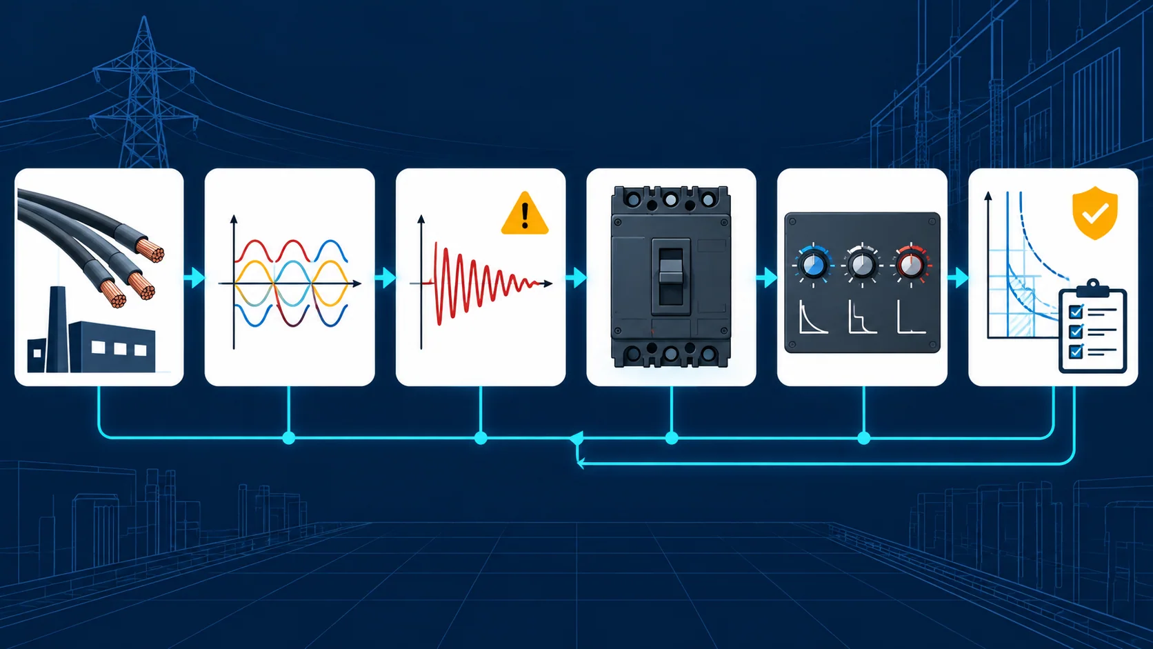
A selection workflow that works
1. Define the circuit and load
Collect nominal voltage, phase arrangement, frequency, load type, continuous-load duty, motor starting or transformer inrush, non-linear loads, ambient, enclosure, conductor material, conductor ampacity, and expected future load.
For a balanced three-phase load, a preliminary current relationship is:
I ≈ P / (√3 × V × η × pf)
where P is real power, V is line-to-line voltage, η is efficiency, and pf is power factor. This is an engineering input, not a final breaker size. Code rules, conductor ampacity, load diversity, starting current, harmonics, and equipment instructions still apply.
2. Calculate or obtain available fault current
The source transformer, utility contribution, generators, motors, inverter-based sources, conductor impedance, and system topology can change the fault level. Use the current short-circuit study or a defensible calculation. Verify the result at the breaker line terminals and for alternate source configurations.
3. Choose the device family and standard
Decide whether the application is governed by IEC, UL, CSA, or another recognized product and installation framework. Confirm whether the device is an MCCB, molded-case switch, fused breaker, supplementary protector, motor-protection device, or another class of equipment.
The UL Solutions MCCB marking and application guide shows why current, voltage, line/load identification, adjustable controls, DC wiring, continuous rating, and special markings must be read from the actual device and guide.
4. Check interruption and equipment ratings
Confirm:
- breaker interrupting rating at the applied voltage;
- panelboard, switchboard, or assembly short-circuit rating;
- series combination or backup protection rules if used;
- peak and short-time withstand requirements where applicable;
- thermal and mechanical duty of the busbar and terminals;
- enclosure and environmental rating.
5. Set the trip functions
The protection settings should protect the conductors and equipment while coordinating with downstream and upstream devices. Review:
| Function | Main question |
|---|---|
| Long-time | Does the overload setting protect the conductor and allow the intended load without nuisance operation? |
| Short-time | Does the delay preserve selectivity without exposing equipment to excessive energy? |
| Instantaneous | Does the pickup allow required inrush while still limiting fault energy? |
| Ground fault | Is the function required, and does it coordinate with the system grounding and downstream protection? |
| Maintenance or energy-reduction mode | Is it available, controlled, labeled, and included in the arc-flash analysis? |
6. Verify connection and installation
Check conductor size and material, terminal kit, lug range, torque, bending space, cable routing, heat dissipation, phase arrangement, handle position, accessories, and manufacturer instructions. Do not drill, tap, or modify a listed enclosure or busbar outside the approved instructions.
7. Record the decision
Keep the breaker catalog or type, frame and trip rating, trip-unit settings, standard, interrupting rating, voltage, enclosure, accessories, coordination result, and installation instructions with the project record. That record is what makes later maintenance and fault investigation possible.
MCCB compared with other protective devices
| Device | Typical role | Main distinction |
|---|---|---|
| MCB | Smaller low-voltage branch or final-circuit protection in its applicable standard and rating range | Usually a narrower current and adjustment range |
| MCCB | Feeder, branch, equipment, or industrial distribution protection | Larger frame options, higher interruption duties, and more configurable trip functions |
| ACB | Low-voltage high-current main or feeder applications | Air circuit breaker construction and functions suited to higher current and system duties |
| Fuse | Overcurrent and short-circuit protection | Current-limiting and replacement characteristics differ from a resettable breaker |
| Molded-case switch | Manual switching or isolation when marked | Does not automatically provide overcurrent protection unless combined with a protective function |
| Supplementary protector | Supplemental protection inside equipment | Not a general substitute for a code-required overcurrent protective device |
These are functional distinctions, not a substitute for the product standard or local code definitions.
Common MCCB misapplications
Selecting only by the handle ampere
The handle or trip rating says little about interrupting capacity, voltage, pole arrangement, enclosure temperature, or coordination. Read the full rating label.
Ignoring available fault current
A breaker with a lower interrupting rating than the available fault current can fail to clear the fault safely. The panelboard or switchboard rating must also be suitable.
Setting long-time protection above the conductor duty
An adjustable trip unit can make a physically large breaker look flexible. It does not permit arbitrary settings. The conductor, termination, load, and code basis must support the selected setting.
Treating Icu, Ics, and AIC as interchangeable
The rating names belong to different product and test frameworks. Compare like with like and document the standard, voltage, and test basis.
Forgetting inrush and coordination
Motors, transformers, capacitors, and power converters can produce expected transients. Raising the instantaneous setting without checking fault energy and selectivity can create a dangerous trade-off.
Using the wrong enclosure or accessory
Trip units, terminals, shunt trips, undervoltage releases, and communication modules are often family-specific. A similar-looking accessory can be incompatible or change the listing.
Assuming a breaker is maintenance-free
Inspection, testing, cleaning, torque checks, and replacement depend on the device, environment, duty, and manufacturer instructions. De-energization and qualified-person procedures apply before opening equipment.
What to request before approval
The approval file should contain:
- one-line diagram and circuit identification;
- load calculation and conductor selection basis;
- short-circuit current at the installation point;
- breaker type, frame, trip unit, voltage, poles, and interruption rating;
- trip settings and coordination or selectivity review;
- enclosure, busbar, terminal, and short-circuit ratings;
- accessory list and wiring diagrams;
- listing, certificate, or conformity information for the jurisdiction;
- installation, torque, and maintenance instructions;
- management-of-change instructions for later breaker or setting changes.
The right MCCB is the one whose ratings, settings, and installation conditions form a defensible protection system. The nameplate is the start of the review, not the end.