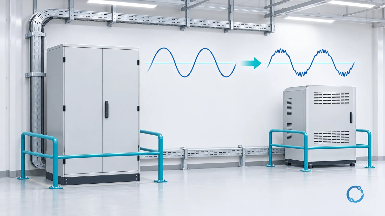
Short answer: “Dirty electricity” is an informal industry phrase for unwanted voltage or current components superimposed on a 50 or 60 Hz power system. These components can distort the mains waveform, add higher-frequency conducted noise or appear as short transients. The phrase is not a standard power-quality quantity, so an engineer should replace it with a measurable phenomenon, frequency range, location and operating condition before diagnosing a problem.
That distinction matters. Harmonic distortion, switching noise in the 2-150 kHz range and a transient spike can all make a waveform look imperfect, but they are not the same event. They require different instruments, different time records and often different corrective measures. A useful investigation begins by asking, “What was measured, at which point, across what bandwidth and while which loads were operating?”
“Dirty electricity” is a label, not one diagnosis
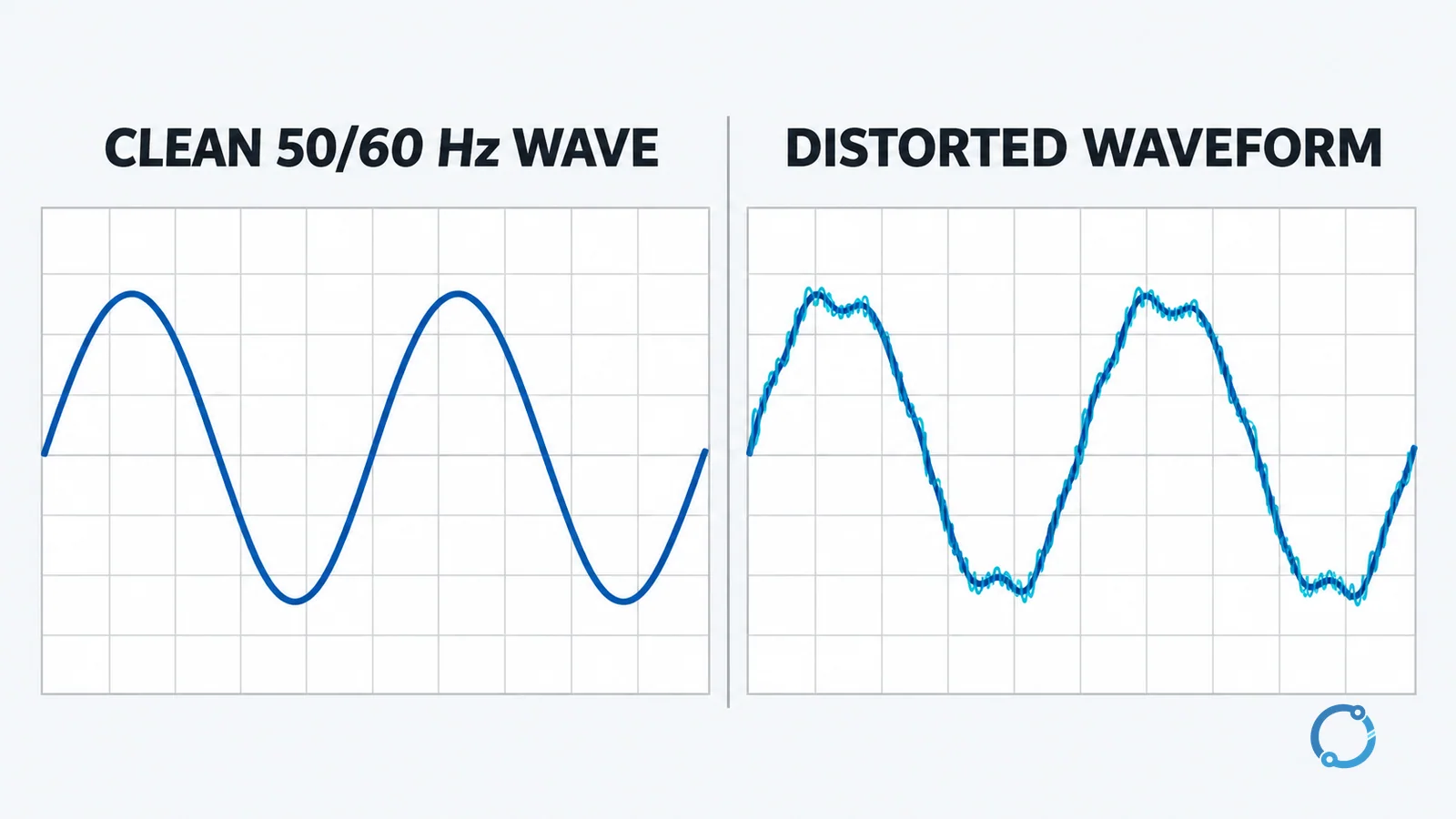
The idealized mains waveform is a sine wave at the system’s fundamental frequency. Real installations contain motors, transformers, rectifiers, variable-frequency drives, LED drivers, chargers, inverters and digital power supplies. These loads can draw current nonlinearly or switch rapidly. The resulting currents interact with source impedance and wiring, so the measured voltage may also depart from a clean sine wave.
Calling all of that “dirty electricity” hides three important dimensions:
- Frequency: Is the component a low-order harmonic, a component in the kilohertz range or a very fast transient?
- Time behavior: Is it present continuously, synchronized with a converter, intermittent with a production cycle or limited to one switching event?
- Measurement point: Is it visible at one equipment terminal, an in-plant point of coupling or the public point of common coupling?
Those dimensions turn a vague complaint into an engineering description. They also prevent a common error: assuming that one filter, one threshold or one instrument can characterize every disturbance called dirty electricity.
Three phenomena hidden inside the phrase
1. Harmonic distortion
Harmonics are steady-state frequency components at integer multiples of the fundamental. On a 50 Hz system, the fifth harmonic is at 250 Hz; on a 60 Hz system, it is at 300 Hz. Nonlinear loads can draw a current waveform that is not sinusoidal even when the applied voltage is close to sinusoidal. That current then creates frequency-dependent voltage drops through the supply impedance.
Harmonic distortion is normally described with a spectrum, individual harmonic magnitudes and an aggregate quantity such as total harmonic distortion. The measurement location is essential. IEEE 519-2022 applies steady-state voltage and current distortion goals at the user point of common coupling, not as one universal equipment-terminal limit. It also distinguishes steady-state distortion from transients and does not cover radio-frequency interference.
The phrase harmonic distortion should be used here. “Harmonic delaying” is not the relevant power-quality term. Power factor is related but separate: displacement, distortion and reactive-power effects should not be collapsed into one label. The power-factor engineering guide explains that adjacent topic.
2. High-frequency conducted noise and supraharmonics
Power-electronic converters switch much faster than the mains fundamental. Their switching action can create voltage and current components in the kilohertz range that travel along power conductors. The 2-150 kHz band is often discussed under terms such as conducted disturbance or supraharmonics, depending on the document and context.
This phenomenon is not simply “more harmonics.” Some components may be related to switching frequency, modulation, control behavior or interaction among several converters. Their amplitude can change when operating mode, load, network impedance or cable configuration changes. A conventional harmonic report may therefore describe the lower-frequency waveform well while revealing little about most of the kilohertz spectrum.
A variable-frequency drive can be one source, but it is not the only one. Solar inverters, chargers, switched-mode power supplies and electronically controlled lighting can also contribute. The separate VFD harmonic mitigation guide covers the source-specific selection problem; this definition page does not prescribe a drive filter.
3. Transients
A transient is a short-duration departure from the normal waveform rather than a continuously present spectral pattern. Switching an inductive circuit, energizing equipment or a lightning-related event can produce a fast voltage change. Its duration, rise time, energy and coupling path matter more than the informal label attached to it.
A transient can contain high-frequency energy, but that does not make it equivalent to steady 2-150 kHz switching noise. A long monitoring record may capture recurring conducted emissions, while a transient may require event triggering and suitable bandwidth. Surge protection is another adjacent task: a surge protective device limits defined transient overvoltages, but it is not a universal cure for steady harmonic distortion or converter noise.
Why engineers talk about a 2-150 kHz “gap”
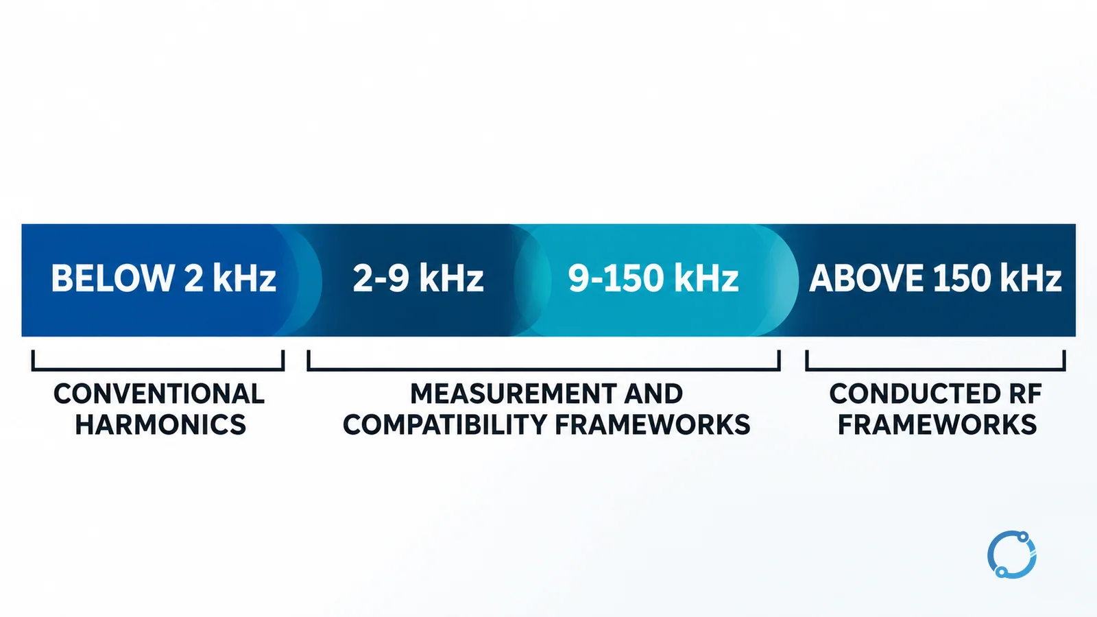
The word “gap” is historically useful but technically easy to overstate. Traditional harmonic practice, power-quality instruments and radio-disturbance standards developed with different frequency boundaries, measurement bandwidths, detector methods and compliance points. For years, the 2-150 kHz region sat between familiar low-order harmonic reporting and mature conducted-radio frameworks. That created fragmented coverage and inconsistent field practice.
It is no longer accurate to say that the entire band has no measurement methods or no applicable limits. The current picture is more specific:
- Below roughly 2 kHz: conventional harmonic and interharmonic analysis commonly describes the steady-state distortion problem. IEEE 519 sets steady-state distortion goals at the point of common coupling within its scope.
- From 2 to 9 kHz: IEC 61000-4-30:2025 includes a conducted-emission measurement method in Annex C.
- From 9 to 150 kHz: the same 2025 edition adds a measurement method in Annex D. IEC 61000-2-4:2024 covers conducted disturbances up to 150 kHz and adds compatibility levels in the 2-150 kHz range for defined industrial in-plant environments.
- Product and environment rules: CISPR PAS 39:2024 adds normative 9-150 kHz mains-emission requirements for certain residential equipment where no relevant dedicated product or product-family standard exists. CISPR 11:2024 covers RF disturbances from 9 kHz for its in-scope industrial, scientific and medical equipment.
The practical gap is therefore a coordination gap, not an empty band. There is no single pass/fail number that applies to every product, every building and every measurement point across 2-150 kHz. The applicable requirement depends on the equipment class, environment, standard, jurisdiction and purpose of the measurement.
The familiar 50th-harmonic boundary illustrates the instrument problem. On a 50 Hz system:
50 x 50 Hz = 2,500 Hz = 2.5 kHz
On a 60 Hz system:
50 x 60 Hz = 3,000 Hz = 3.0 kHz
An analyzer configured or designed to report only through the 50th harmonic therefore stops at 2.5 or 3.0 kHz. It does not necessarily see most of the 2-150 kHz band. That statement is narrower and more accurate than saying that every conventional power-quality instrument is blind above 2 kHz: bandwidth and analysis functions vary by instrument.
What the disturbances can do to equipment
Frequency-dependent loss and heating
Higher-frequency current does not use conductors, windings and magnetic components in exactly the same way as the fundamental current. Skin and proximity effects change current distribution as frequency rises. Additional eddy-current, dielectric and magnetic losses may appear in components that carry or absorb the disturbance. Capacitors can also experience extra ripple-current stress. The engineering consequence can be temperature rise or reduced margin, but the result depends on spectrum, amplitude, impedance and component construction; the presence of a kilohertz component alone does not prove overheating.
Triplen harmonics from nonlinear single-phase loads can add in a shared neutral under relevant three-phase arrangements. That separate design question belongs in the neutral-conductor sizing guide for harmonic loads, not in a generic dirty-electricity rule.
Functional disturbance and nuisance operation
Conducted noise can enter sensing, control or protection circuits through the supply or through coupling paths. The result may be intermittent resets, false inputs, unstable control behavior or unwanted operation of a residual-current device. These symptoms do not prove one cause. An RCD trip, for example, can also indicate real leakage, wiring faults, aggregate filter current or an unsuitable device type. Protection must never be bypassed to make the symptom disappear.
Interference with communication and signaling
Power-line communication deliberately uses the mains as a signal path. Unintentional kilohertz emissions can occupy or raise the noise floor in part of the same conducted environment, affecting reception or reliability. Similar coupling can disturb nearby control or communication circuits when layout, shielding, bonding or cable routing permits it. The correct response is to identify the coupling path, not to assume that every communication problem comes from the mains.
Ground-referenced noise also deserves a separate diagnosis. Removing protective earth is unsafe and can conceal rather than solve the coupling mechanism. The computer grounding and noise diagnosis explains how to investigate without defeating protective grounding.
How engineers measure it
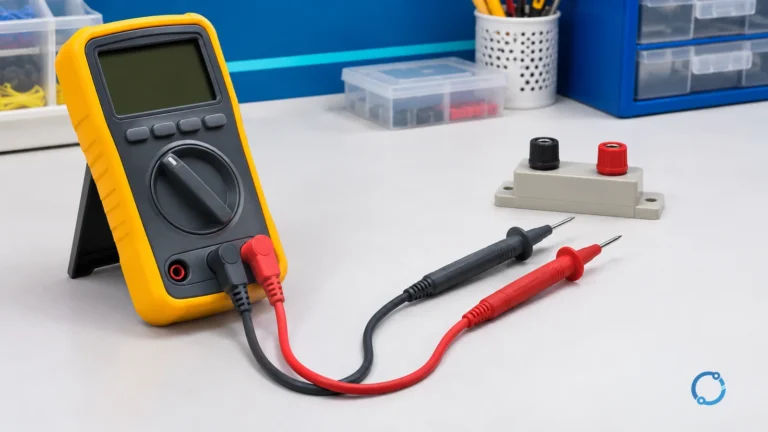
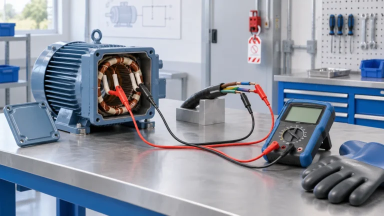
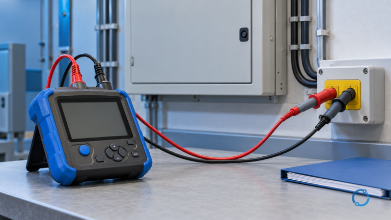
A defensible investigation uses a Class A power-quality instrument under the relevant IEC 61000-4-30 method when comparable, repeatable mains measurements are required, and adds equipment with verified 2-150 kHz bandwidth when that range is part of the question. A practical campaign may monitor a representative operating week, but one week is an engineering choice, not a universal IEC duration; the record must include the load cycles and events that produce the symptom. A suitable spectrum instrument and current probe can then characterize the kilohertz components, while controlled circuit or load switching can help associate a source with the observed spectrum. Such work belongs to qualified personnel using correctly rated instruments and safe connection procedures. For the complete sequence, use the power-quality measurement and monitoring plan.
How engineers mitigate it
Mitigation should follow the measured source and coupling path:
- Control the source. Correct defective equipment, verify converter configuration and use the equipment maker’s documented EMC provisions where applicable.
- Separate circuits and routes. Reduce shared impedance and unwanted coupling by reviewing supply segregation, cable routing, bonding and physical separation.
- Apply a verified filter. Select filtering for the measured differential-mode or common-mode spectrum, source impedance, load current and safety requirements; a generic plug-in device is not an engineering specification.
- Use isolation only for a defined path. An isolation transformer can change galvanic and common-mode relationships in some systems, but it does not automatically remove every high-frequency component. Its earthing, shielding and downstream arrangement determine the result.
Each measure should be followed by the same measurement at the same point and operating condition. Otherwise, a quieter-looking trace may reflect a changed setup rather than a real correction.
A boundary on health claims
“Dirty electricity” is not a medical diagnosis or a recognized health-exposure metric. The World Health Organization does not confirm a causal link between low-level electromagnetic-field exposure and the broad nonspecific symptoms often attributed to it. This article therefore makes no health claim and recommends no health-oriented filter. Its scope is limited to measurable engineering effects on electrical equipment and systems.
FAQ
Is dirty electricity the same as harmonic distortion?
No. Harmonic distortion is one measurable phenomenon involving integer multiples of the fundamental frequency. The informal phrase “dirty electricity” may also refer to conducted noise in the kilohertz range or to short transients, which require different measurement methods.
Why is the 2-150 kHz range called a gap?
It historically sat between conventional low-order harmonic practice and established radio-disturbance frameworks, so measurement and limits were fragmented. Current IEC and CISPR documents now cover important parts of the band, but there is still no single universal installation limit for every product and environment.
Can a standard power-quality analyzer measure 2-150 kHz noise?
Only if its specified bandwidth and analysis functions cover that range. An instrument limited to the 50th harmonic reaches 2.5 kHz on a 50 Hz system or 3.0 kHz on a 60 Hz system, so it misses most of the band.
Can a surge protector remove dirty electricity?
An SPD is intended to limit defined transient overvoltages. It is not a general solution for steady harmonic distortion or recurring 2-150 kHz converter noise. The disturbance must be measured and matched to an appropriate mitigation method.
What is the first step when dirty electricity is suspected?
Define the symptom, measurement point, operating condition and frequency range before choosing a remedy. Use correctly rated instruments and qualified personnel, then compare the spectrum and time record with load operation to identify the source and coupling path.
Sources
- IEEE 519-2022 – Harmonic control in electric power systems
- IEC 61000-4-30:2025 – Power quality measurement methods
- IEC 61000-2-4:2024 – Compatibility levels for industrial power distribution
- IEC 61000-4-7 – Harmonic and interharmonic measurement guidance
- CISPR PAS 39:2024 – Conducted emissions from 9 kHz to 150 kHz
- CISPR 11:2024 – RF disturbance limits and measurement methods