
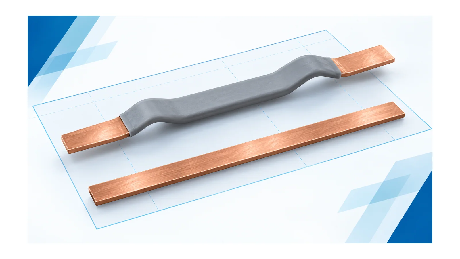
A flexible insulated link can be useful for an offset connection; a rigid bare copper rail can suit a stable distribution backbone. Neither is automatically the smaller, cooler or safer solution. Compare two complete layouts serving the same endpoints and electrical duty, including exposed ends, support positions and service access.
This guide concerns guarded industrial low-voltage (LV) panels. Its typical comparison is an insulated flexible copper-foil link versus a fixed bare rail. The outcome is a layout acceptance record, not a generic ampacity table or permission to work on energized conductors.
Flexibility and insulation are independent attributes
“Flexible” describes mechanical behavior; “insulated” describes an electrical boundary. A conductor can be flexible and bare, or rigid and insulated. Do not assign all advantages or restrictions to one of these words when they arise from the other.
In the typical comparison here, the flexible link has an insulating covering along part of its length and engineered terminal ends. The bare rail relies on the assembly’s spacing, barriers and enclosure arrangements. Both need complete interface and assembly evidence.
The broader choice between a busbar system, distribution blocks and cables is a separate architecture question. Resolve it with panel busbar versus block-and-cable distribution before comparing two conductor layouts within that architecture.
Five questions decide the panel comparison
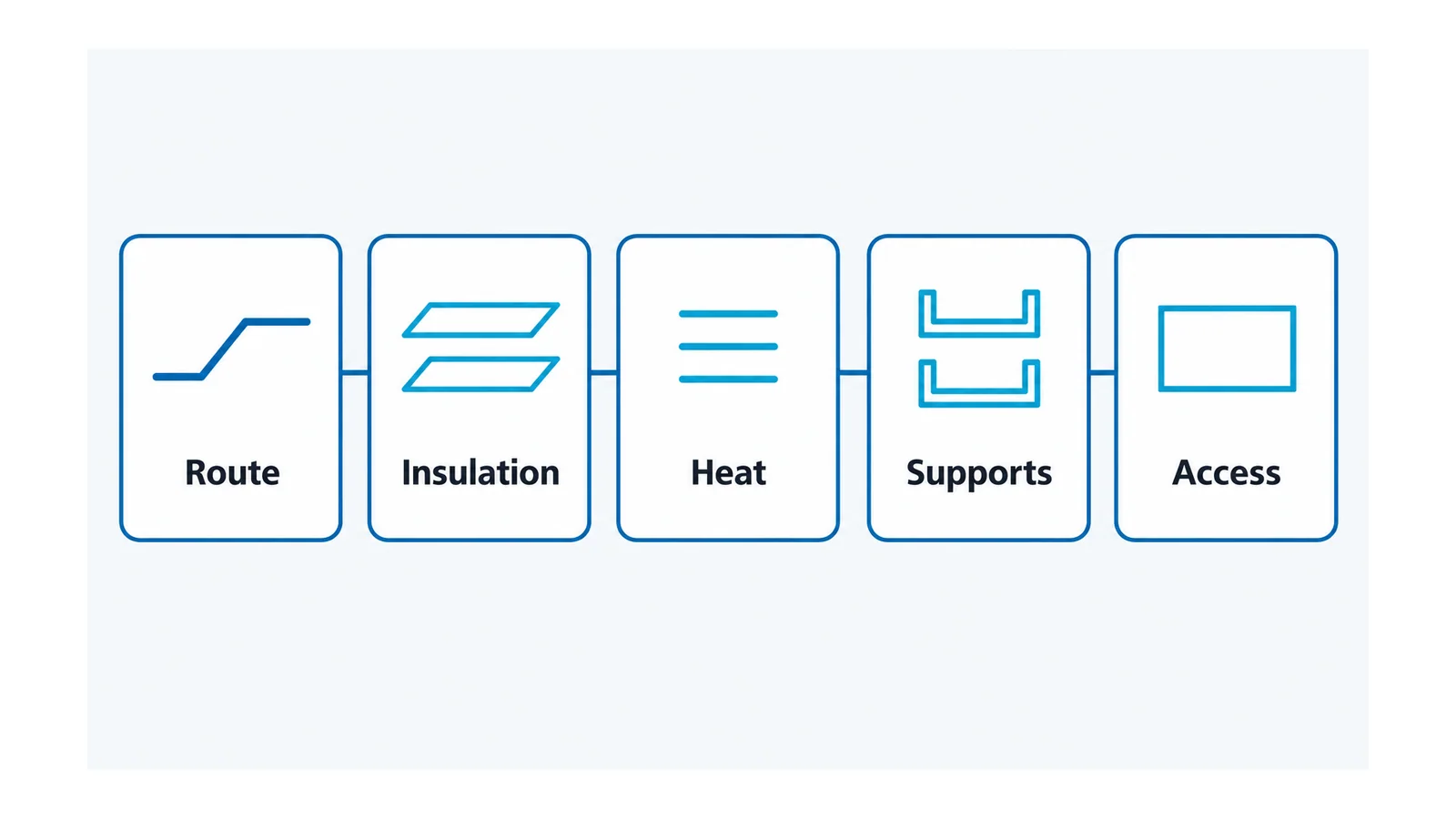
| Layout check | Flexible insulated link | Fixed bare rail | Acceptance question |
|---|---|---|---|
| Route | Formed shape and allowed bending determine the actual envelope | Rail sections and transitions determine the actual envelope | Does the complete installed route fit without prohibited bending, fouling or terminal strain? |
| Insulation | Covering, transitions and exposed ends all matter | Air/surface paths, barriers and enclosure all matter | Is each electrical boundary resolved under the intended conditions? |
| Heat | Covering, link shape and end losses affect the thermal assessment | Surface condition, rail placement and joints affect the thermal assessment | Is temperature-rise evidence valid for this configuration? |
| Supports | Flexible-section movement and terminal force need control | Rail spans and joints need suitable restraint | Are supports and interfaces acceptable for the declared fault duty? |
| Access | A formed link may help or obstruct nearby service space | A rail layout may offer clear access or require awkward removal | Can qualified personnel inspect and service the arrangement safely under the approved procedure? |
1. Compare the installed envelope, not the copper width
For an insulated link, include the covering, formed bend, terminal transition, motion allowance and nearby objects. For bare rail, include bends or joints, supports, barriers and the required electrical spacing. Measure both candidates in the same panel coordinate system.
Flexibility may solve an offset without an additional rigid transition, but it can also create a loop that occupies depth or obstructs a device. A straight rail may be efficient in a repeated distribution layout. Do not declare a percentage space saving without complete comparable drawings.
Specify forming limits separately from service motion. A link that may be shaped during assembly is not necessarily rated for repeated movement. Any route that imposes an unaccepted load on a breaker terminal remains unresolved, regardless of whether it physically fits.
2. Treat the insulation system and the exposed ends separately
An insulating covering does not eliminate the electrical design around terminations. Identify where the covering ends, where conductive metal remains exposed, and where the relevant air and surface paths run.
IEC 60664-1:2020+AMD1:2025, from the International Electrotechnical Commission (IEC), addresses insulation coordination, including clearance, creepage and solid insulation within its LV scope. The public scope does not support a blanket reduction in spacing merely because a conductor is coated. IEC insulation-coordination scope
The required distances or insulation performance depend on the applicable assembly requirements and conditions. Have the responsible designer resolve voltage duty, environment, interfaces and the adopted standard. Do not take a coating thickness or color as proof of an acceptable insulation system.
Likewise, bare copper is not necessarily an accessible live part in the finished assembly. Its guarding and spacing may be provided by the complete arrangement. Conversely, a covered length does not make exposed ends safe to touch.
3. Recheck thermal behavior in the actual arrangement
Compare total link and joint losses under the same loading conditions, then how each layout transfers heat. Insulation changes the conductor’s thermal boundary, and coverage near a joint matters to that assessment. The institutional copper-busbar guide discusses these physical effects; its older standards references are not adopted here as current acceptance limits. Copper-busbar insulation guidance
Do not assume insulation always produces a hotter conductor, or that exposed copper always runs cooler. Geometry, surface conditions, airflow, neighboring losses and contacts also change the result. Use applicable configuration-specific evidence rather than comparing isolated catalogue currents.
Equal copper section is only one input. The copper-busbar ampacity and derating guide covers that separate capacity question; this page asks whether the evidence remains valid in the proposed panel layout.
4. Resolve supports and fault forces independently of flexibility
A flexible link can still transmit forces to its ends and require restraint. A rigid rail still needs an acceptable span, joint arrangement and support system. Neither flexibility nor an insulating covering proves short-circuit performance.
IEC 61439-2 covers power switchgear and controlgear assemblies; the applicable verification basis concerns the complete configuration, not just the conductor sample. IEC assembly scope
Record support type and position, terminal interfaces, declared electrical duty and relevant evidence for each alternative. If the route, support spacing or insulation system changes, ask the assembly designer which parts of the earlier verification can still be used.
5. Preserve a usable, safely controlled service route
Check access to the actual fasteners and interfaces, not simply visibility of copper. Review how a connection is inspected, disconnected and replaced without damaging adjacent insulation or loading a device terminal. Record any assembly sequence dependencies.
Service access is a layout property, not authorization for live work. Isolation and absence-of-voltage verification remain necessary under the applicable procedure. Occupational Safety and Health Administration (OSHA) regulation 1910.333 provides a US general-industry reference; the correct local rules, qualified-person requirements and protection arrangements must govern the work. OSHA electrical work practices
Example: an offset breaker feeder
Consider a hypothetical connection between a fixed distribution rail and an offset breaker terminal. No ratings, dimensions or measured savings are assumed.
Option A is an insulated flexible link shaped to the offset. Option B is a bare rigid connection with the required transitions, supports and barriers. Hold the endpoints, electrical duty, panel boundaries and access requirements constant.
For Option A, acceptance depends on the formed-envelope drawing, permitted bending and terminal loading, the exposed-end boundary, thermal evidence and fault restraint. Reject the route if it bends through a prohibited transition or prevents access to the mating interface.
For Option B, acceptance depends on the complete rigid-route drawing, joint/interface design, spacing and barriers, thermal evidence and support arrangement. Reject the route if its added transition conflicts with the panel’s accepted electrical or service envelope.
If both pass, compare fabrication, inspection and replacement requirements on documented terms. If neither passes, revise the layout. A hypothetical compactness preference is not adequate evidence to release either one.
For the surrounding conductor-to-enclosure design iteration, use compact switchgear busbar sizing.
What makes the comparison complete?
Retain equal-duty drawings for both alternatives, the actual formed envelope, insulation boundaries including ends, thermal basis, fault/support evidence and service plan. Mark each unresolved requirement explicitly and assign its evidence owner.
Choose the accepted panel configuration, not a conductor adjective. That keeps an attractive flexible route from bypassing insulation or support checks, and keeps a familiar bare rail from bypassing layout and access checks.
Sources
- IEC 60664-1:2020+AMD1:2025: public insulation-coordination scope.
- IEC 61439-2:2020: public power-assembly scope.
- Copper for Busbars — Guidance for Design and Installation, 2014: physical insulation and heat-transfer principles.
- OSHA 1910.333: US general-industry work-practice boundary.