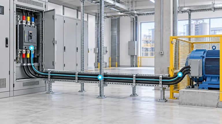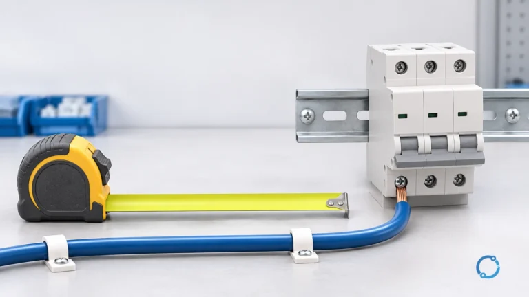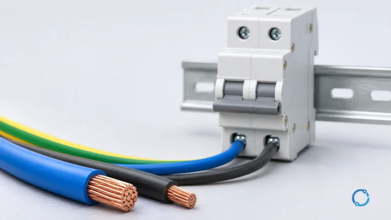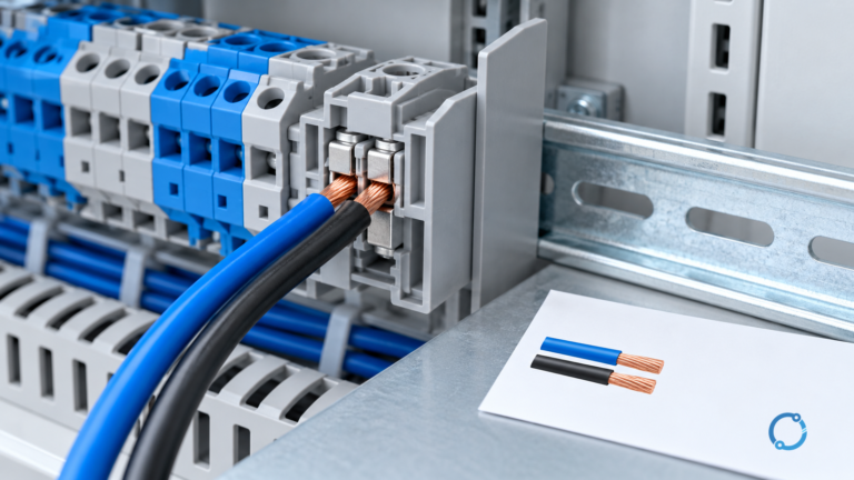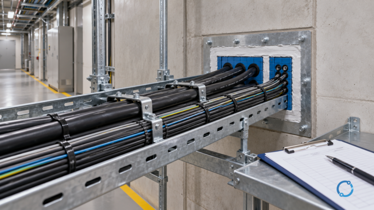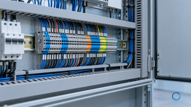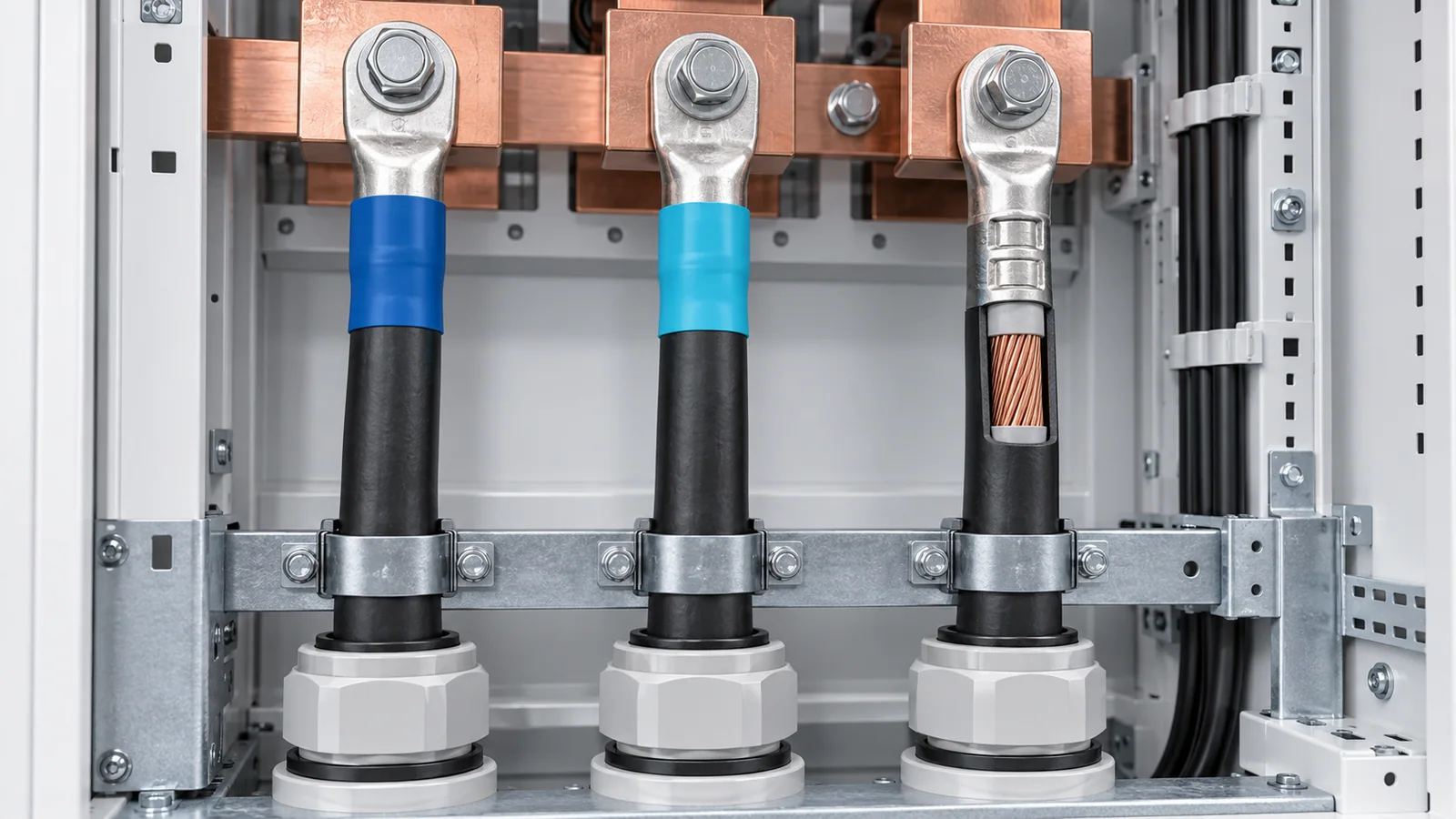
A reliable low-voltage cable termination is a controlled electrical and mechanical interface. The connector must match the conductor material, size, strand class, temperature rating, and equipment terminal; preparation must not nick or lose strands; the specified crimp or torque must be applied with the correct tool; and the finished connection needs insulation, clearance, strain relief, and environmental protection appropriate to the installation.
Most termination failures are not caused by one dramatic mistake. They develop from resistance, heat, movement, contamination, corrosion, or electric-field concentration created by a mismatch or an inconsistent process.
What counts as an LV cable termination?
For this article, the scope is power-cable terminations for circuits rated up to 1 kV AC; jurisdictional definitions of low voltage may differ. Common termination points include switchboards, circuit breakers, disconnects, motor-control centers, motors, transformers, busbars, junction boxes, and industrial equipment.
Typical components include:
- compression lugs;
- mechanical or shear-bolt lugs;
- pin terminals and ferrules for suitable stranded conductors;
- terminal blocks and equipment pressure terminals;
- cable glands, cord grips, clamps, or cleats for entry and strain control;
- heat-shrink, cold-shrink, boots, sleeves, phase barriers, or insulating covers;
- bonding hardware for armor, screen, metallic sheath, or enclosure where the cable design requires it.
LV termination practice differs fundamentally from medium-voltage shielded cable termination and its stress-control requirements. MV work manages semiconductive screens and electric-field stress at the shield cutback. LV cable generally does not use that stress-control geometry, but it still needs adequate insulation, creepage, clearance, sealing, and mechanical support.
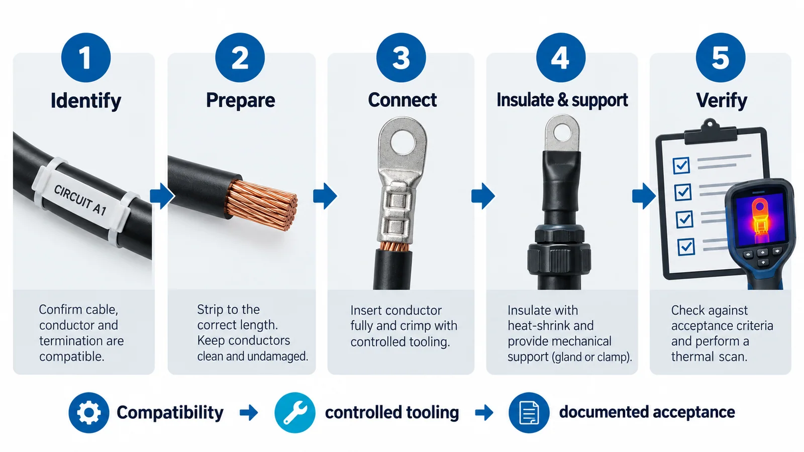
Match the connector to the conductor
The first selection rule is compatibility. Record:
- copper or aluminum conductor;
- solid, stranded, compacted, sector-shaped, or flexible conductor class;
- metric cross-sectional area or AWG/kcmil size;
- number of conductors permitted in the terminal;
- insulation material and temperature rating;
- cable voltage rating and installation environment;
- equipment terminal geometry and available space;
- short-circuit duty and mechanical forces;
- required certification or listing for the jurisdiction.
IEC 61238-1-1:2018 defines type-test methods and requirements for compression and mechanical connectors used on power cables up to 1 kV (Um 1.2 kV) with copper or aluminum conductors within its stated size and temperature range. Its scope includes electrical, short-circuit, and mechanical tests. Passing a product standard does not remove the need to install the connector with the conductor and tools for which it was evaluated.
In the United States, OSHA requires terminals used for more than one conductor and terminals used with aluminum to be identified accordingly. OSHA 1910.303(c) also requires connections that provide good contact without damaging conductors and recognizes pressure connectors, solder lugs, or suitable splices within its scope.
Compression lugs
A compression termination creates contact pressure by plastically deforming the barrel around the conductor. The complete system includes the lug, conductor, die, tool, number and location of crimps, and preparation method.
Key controls are:
- use the specified lug series and conductor range;
- use the specified die profile, size, and calibrated tool;
- strip to the correct length without nicking strands;
- fully insert the conductor and confirm it where an inspection window exists;
- follow the required crimp sequence and orientation;
- do not add or omit crimps based on appearance;
- keep contact surfaces free of incompatible contamination;
- apply oxide-inhibiting compound only where the connector instructions require or permit it.
A crimp that “looks tight” is not objective evidence. Tool-cycle completion, die marks, crimp count and location, conductor insertion, and documented inspection provide stronger verification.
Mechanical and shear-bolt lugs
Mechanical lugs use screws or bolts to develop contact pressure. Shear-bolt designs are engineered so the bolt head breaks at a controlled torque condition, often allowing a defined conductor range without a hydraulic crimper.
These connectors still require exact compatibility and preparation. Important checks include conductor centering, insert or sleeve selection, bolt sequence, specified torque or shear behavior, surface treatment, and the finished profile under the insulation system.
Never substitute a generic torque value. Thread size alone does not determine tightening torque; terminal design, conductor material, lubrication, plating, fastener grade, and test method all matter. Use the current instructions for the exact connector and equipment.
Ferrules and flexible conductors
Fine-stranded conductors can spread, creep, or be damaged when clamped in a terminal not designed for that conductor class. A ferrule can consolidate strands for a compatible terminal, but a ferrule is not universally required or permitted.
Verify that:
- the terminal accepts the conductor class and ferrule type;
- the ferrule barrel matches conductor area and strand construction;
- the crimp tool and profile are specified;
- the insulated collar does not obstruct insertion;
- twin ferrules are used only where the terminal allows two conductors;
- the terminal torque and inspection method remain valid with the ferrule.
UL Solutions’ connector certification overview identifies UL 486A-486B for wire connectors and UL 486F for bare and covered ferrules. This helps define the relevant product-evaluation families; the installation still follows the product marking, equipment instructions, and applicable code.
Cable entry, support and strain relief
The electrical joint should not carry cable weight, pulling force, vibration, or bending moment. Glands, clamps, cleats, and supports transfer mechanical load to the enclosure or structure.
For each entry, check:
- gland or connector range matches the cable outside diameter;
- enclosure ingress rating is maintained where required;
- armor or metallic sheath is bonded or isolated according to the cable system design;
- bending radius is respected near the termination;
- cable cleats or supports withstand normal and short-circuit forces;
- thermal expansion and equipment vibration do not load the terminal;
- sharp edges are bushed and openings are closed.
OSHA 1910.305 requires protection from abrasion at cabinet and box entries and requires strain relief for flexible cords and cables so pulling is not transmitted directly to joints or terminal screws. Applicability depends on the installation and jurisdiction.
Insulation, creepage and clearance
After the conductor is connected, exposed conductive length must remain within the terminal or be restored with an approved insulation system. Phase boots, heat-shrink, barriers, and cable breakout components may be used where the equipment design requires them.
Do not assume that more tape fixes a poor geometry. The design must preserve:
- air clearance between live parts and between live parts and earth;
- creepage distance along insulating surfaces;
- conductor bend radius and phase spacing;
- compatible temperature and flame performance;
- resistance to moisture, contamination, UV, chemicals, and tracking where relevant;
- access for inspection without compromising barriers.
IEC 60364-5-52 addresses selection and erection of wiring systems in low-voltage installations. Exact clearance and creepage requirements may instead come from the equipment standard, assembly standard, insulation-coordination rules, or local installation code; verify the governing document rather than copying a generic distance.
A controlled termination workflow
1. Identify and isolate
Confirm the cable, circuit, destination, phasing, conductor data, and drawings. De-energize and secure all sources, including backfeeds and stored energy, under the employer’s approved procedure. Test for absence of voltage with suitable equipment.
2. Inspect materials and environment
Verify connector, kit, conductor, terminal, gland, tools, dies, calibration status, shelf life, and installation conditions. Stop if parts are damaged, wet, contaminated, corroded, expired, or outside their temperature range.
3. Plan the geometry
Set cable support, phase lengths, bend radii, lug orientation, and service loop before cutting. A termination should align naturally with the terminal without using the fastener to pull it into place.
4. Prepare the cable
Remove sheath and insulation to the specified dimensions using tools that will not score the conductor. Preserve required armor, screen, bedding, fillers, and bonding components. Do not remove strands to make a conductor fit.
5. Make the connection
Install the connector using the specified crimp system, bolt sequence, torque, or shear method. For bolted palm connections, prepare mating surfaces and hardware exactly as the equipment instructions require.
6. Restore insulation and sealing
Apply boots, sleeves, barriers, gland seals, or phase identification without trapping contamination or creating sharp edges. Ensure the insulation component has fully recovered or seated before testing.
7. Inspect and test
Use a documented checklist. Depending on the installation, verification may include visual inspection, tool records, torque witness, conductor identification, continuity, insulation resistance, protective-conductor continuity, phase rotation, and thermographic baseline after controlled energization and loading.
Testing requirements depend on the cable, equipment, local rules, and commissioning plan. A passing insulation-resistance test does not prove that a connector has adequate contact pressure.
Failure modes and what they reveal
| Symptom | Likely mechanism | Verification focus |
|---|---|---|
| Localized heating at lug or terminal | High contact resistance, wrong connector, inadequate crimp/torque, contamination | De-energized inspection, installation records, conductor/connector match, thermal comparison under balanced load |
| Discoloration or melted insulation | Sustained overheating or arcing | Load history, protection operation, contact damage, enclosure temperature |
| Pulled-out conductor | Inadequate mechanical retention or strain relief | Connector system, insertion depth, crimp record, cable support |
| Green/white corrosion products | Moisture ingress or dissimilar-material reaction | Gland/seal, environment, copper/aluminum interface, approved compound |
| Broken strands near barrel | Nicks, over-crimp, wrong die, vibration, bend stress | Preparation method, tool/die, support, bending geometry |
| Loose bolted palm | Wrong hardware, torque method, joint settlement, vibration | Exact assembly instructions, locking method, surface condition |
| Surface tracking | Contamination, moisture, insufficient creepage, damaged insulation | Insulation geometry, environment, cleaning and sealing |
| Repeated protective-device operation | Fault, overload, phase loss, or heating—not necessarily the breaker | Current balance, insulation, connection resistance, motor/load condition |
Do not re-torque a hot or energized connection as a first response. Isolate the circuit, determine whether the joint and connected equipment have suffered thermal or arc damage, and replace components when the acceptance criteria are no longer met.
Acceptance checklist
- Correct cable, circuit, phase, and destination
- Connector approved for conductor material, size, strand class, and quantity
- Terminal and connector ratings suitable for voltage, current, temperature, and environment
- Correct strip length with no nicked or missing strands
- Full conductor insertion documented
- Correct die/tool/crimp sequence or bolt/torque/shear method
- Lug palm and terminal aligned without mechanical preload
- Required bonding, grounding, gland, cleat, and strain relief complete
- Insulation, barriers, creepage, clearance, and enclosure sealing restored
- Labels and phase identification durable and correct
- Inspection and electrical test results recorded
- Covers, shutters, interlocks, and enclosure hardware restored before energization
Bottom line
LV cable termination quality comes from compatibility and process control. Match the connector to the conductor and terminal, prepare without damage, use the specified tooling and torque, support the cable independently, restore insulation and environmental protection, then verify the work with documented acceptance criteria. If a connection runs hot, investigate the entire interface rather than treating tightening as a universal cure.
For related installation topics, browse the Low Voltage articles. When investigating supply disturbances rather than a localized connection defect, use the voltage sag and swell diagnostic guide.