
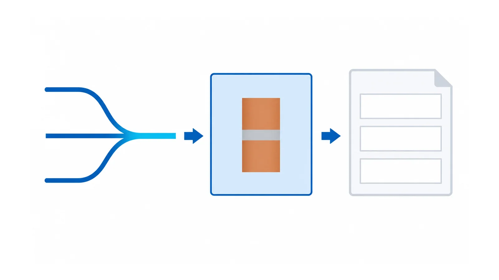
A terminal block’s current rating is usable only with its declared conditions. To accept an actual load, match the conductor and preparation, operating duty, local temperature, arrangement and accessories to the applicable evidence. Then check every shared segment—not just the terminal connected to one branch.
There is no universal “use 80% of the rating” rule for terminal blocks. A blanket margin cannot resolve missing rating conditions, an overloaded bridge or an unverified hot enclosure. This worksheet concerns supported copper-conductor terminal strips in industrial low-voltage panels; PCB connectors, protective-conductor paths and fuse terminals may require different evidence.
For the broader function-to-device decision, use terminal-block selection for electrical panels. Here the narrower question is: can this specified current path carry this load profile in this arrangement?
1. Establish what the printed rating actually covers
Capture the exact terminal designation and approval/rating basis. Record the conductor material, cross-section, class and preparation associated with the rating, plus any relevant ambient, mounting or simultaneous-loading conditions. Include the exact accessories and connected devices.
IEC 60947-7-1:2025 covers industrial or similar supported terminal blocks for copper conductors, including specified test-disconnect arrangements. Its public scope does not provide a current rating for an arbitrary conductor/terminal combination. Do not manufacture a temperature-rise limit or derating curve from that scope.
The sixth edition of UL 1059, published in December 2024, separately makes end-application suitability dependent on actual service conditions. Product-standard compliance alone does not establish suitability in the finished equipment.
Do not mix a current value from one approval route with conductor conditions from another. The UL/IEC terminal-marking guide addresses that reading task. An IEC value and a UL value are not two interchangeable options from which to choose the larger number.
2. Draw currents through terminals and bridges
For a common supply feeding several branches, the incoming connection carries the combined simultaneous current. A bridge segment near the supply may carry more than a segment farther along the strip. Its allowable duty may also differ from the terminal it fits.
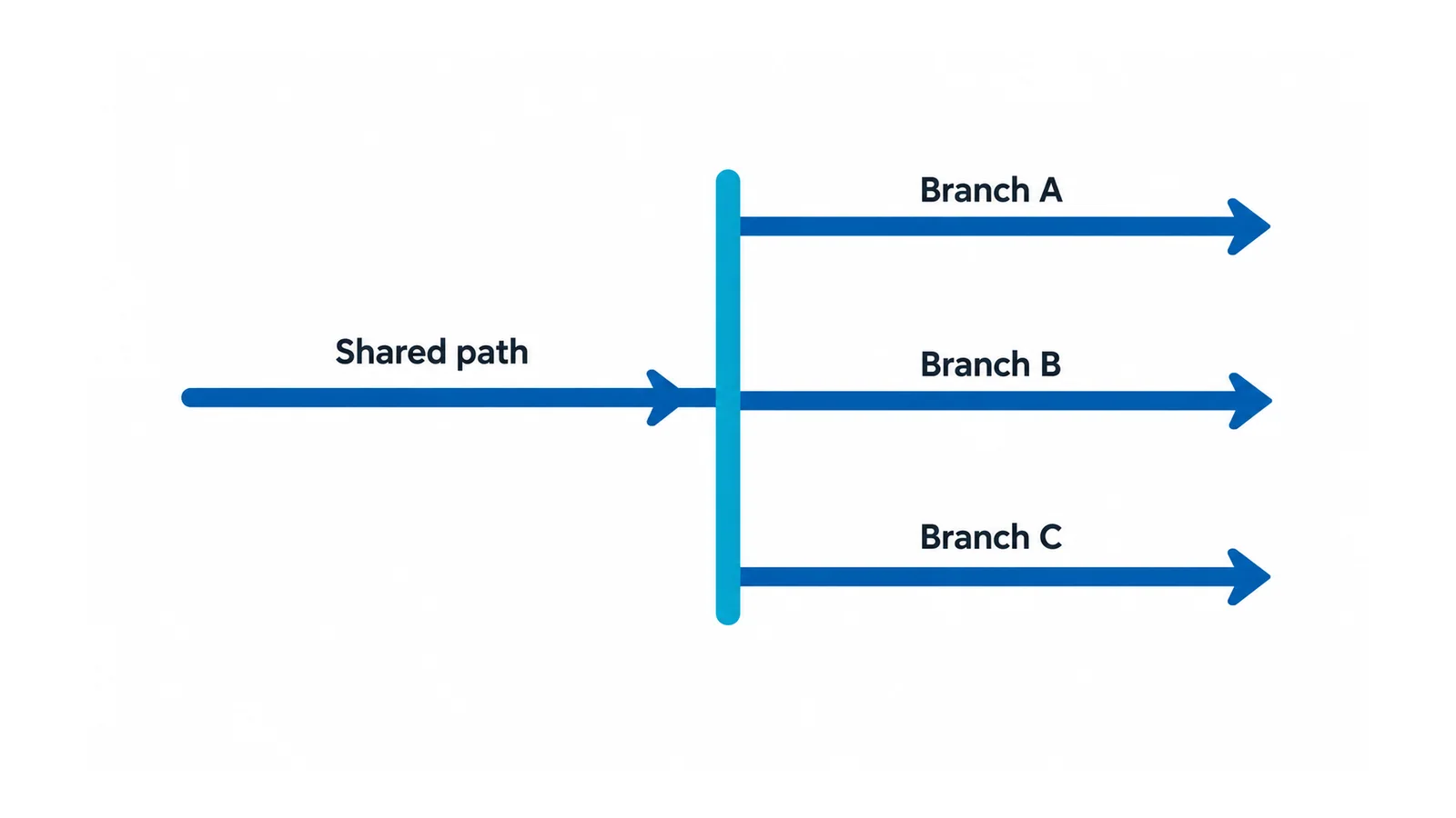
Consider this hypothetical direct-current distribution path, with three same-direction loads operating simultaneously:
| Branch | Assumed current | What it contributes to the shared incoming path |
|---|---|---|
| A | 8 A | 8 A |
| B | 6 A | 6 A |
| C | 4 A | 4 A |
| Shared incoming connection | 18 A | 8 + 6 + 4 = 18 A |
The first common segment sees 18 A, not the largest branch value of 8 A. In an idealized linear route passing A, B and C in that order, the segment after A carries 10 A and the segment after B carries 4 A. Actual bridge topology and supply-entry position must be drawn before using those results.
These currents are arithmetic examples, not product ratings. For AC circuits, phase relationships, harmonic content and topology can change the current summation; do not add unsigned RMS values as though every case were this DC example.
3. Separate heating duty from peak-current capability
Continuous operation, cyclic operation, startup pulses and short circuits ask different questions. An average current can conceal substantial heating because resistive loss varies with the square of current.
For a repeating profile, an illustrative RMS current is:
I_rms = √[Σ(Iᵢ² × tᵢ) / Σtᵢ]
Here Iᵢ is current in amperes and tᵢ is the duration of each interval in the same time unit. This is a heating-equivalent current only under the simplified assumption that the relevant path resistance is constant.
Suppose a path carries 20 A for 10 seconds and 5 A for 50 seconds in each 60-second cycle:
- Arithmetic average = (20 × 10 + 5 × 50) / 60 = 7.5 A.
- RMS = √[(20² × 10 + 5² × 50) / 60] = √87.5 = 9.35 A.
- With a hypothetical constant total path resistance of 2 milliohms, average resistive loss = I_rms²R = 87.5 × 0.002 = 0.175 W.
The units reduce to A²Ω = W. Using the arithmetic average would predict only 0.1125 W, understating this model’s heating. The resistance and currents above are invented educational inputs, not measurements or acceptance thresholds.
This calculation does not predict the terminal temperature or prove that 20-A pulses are permissible. Contact resistance, heat dissipation and thermal time constants can change during operation. Verify peak duty and duration separately, and use the applicable thermal evidence for the actual installation. A short-circuit event requires a separate protection/withstand assessment.
4. Match the load to the installed thermal conditions
Use local terminal-area conditions, not merely the room temperature. Identify neighboring heat sources, the number of loaded levels or poles, grouping, ventilation and relevant abnormal operating states. A fan-dependent design needs the approved treatment of unavailable cooling.
Where the selected component provides applicable derating or configuration data, use that exact information within its scope. Where it does not, obtain an assembly-design assessment or suitable verification evidence; do not invent a percentage reduction per degree Celsius.
IEC 61439-1:2020 addresses LV assembly construction and verification, together with the applicable product part. A suitable terminal does not itself establish the panel’s temperature-rise performance.
Material and contact behavior also affect losses. The terminal-block materials and contact-resistance guide develops that mechanism. A measurement showing the current below a catalog number does not rule out a poor connection or inadequate heat transfer.
5. Complete the acceptance register
Use one row for each electrically distinct segment and each relevant operating case. Do not hide the incoming connection or common bridge inside a generic “terminal strip” row.
| Register field | Required entry | Hold condition |
|---|---|---|
| Path identity | Drawing reference, terminal and accessory designations | Unidentified bridge or unrecorded topology |
| Actual current duty | Continuous, cyclic and peak currents with timing and simultaneity assumptions | Shared current omitted or average substituted for heating duty |
| Connection conditions | Accepted conductor, preparation, number of conductors and installation instructions | Combination not supported by evidence |
| Thermal basis | Local conditions, adjacent loading and applicable configuration evidence | Only room temperature or material temperature rating supplied |
| Fault/protection basis | Available duty and applicable protected-path or assembly evidence | Normal-current rating used as short-circuit evidence |
| Disposition | Pass, hold or revise; evidence reference and responsible approver | Any critical assumption remains unresolved |
“Pass” means the responsible design review has accepted the documented application under its applicable criteria. It is not a certification issued by this worksheet. The limiting condition governs the path; if a bridge fails, choosing a larger branch terminal alone does not repair the design.
6. Preserve the accepted conditions in service
Reopen the review after changing conductor preparation, bridge positions, loading, enclosure cooling or adjacent equipment. A replacement that physically fits may not retain the accepted current path or conditions.
In US general-industry applications, OSHA 1910.303 addresses equipment suitability, heating, connections and use according to listing/labeling instructions. This is a jurisdiction-specific reference, not a universal terminal rating formula.
For inspection or alteration, qualified personnel must use the applicable isolation, lockout/tagout and absence-of-voltage verification procedure; OSHA 1910.333 provides the US general-industry work-practice boundary. Do not tighten a live connection or bypass protection to collect a test result.
If an installed strip overheats despite apparently acceptable loading, the next task is diagnosis, not a larger nameplate number. The LV switchgear operating-temperature guide separates enclosure-wide conditions from localized problems.
Sources
- IEC 60947-7-1:2025: copper-conductor terminal-block public scope.
- UL 1059, sixth edition: terminal-block scope and end-application suitability.
- IEC 61439-1:2020: assembly general rules and verification scope.
- OSHA 1910.303 and 1910.333: bounded US equipment and work-practice requirements.